Rotolinear clamping cylinder

A clamping cylinder, clamping position technology for clamping, climate sustainability, final product manufacturing, etc., that can solve problems that hinder automatic operation, cannot ensure stack retention, cannot detect clamping position or release position, etc. , to achieve the effect of increasing service life, reducing price and weight, and reducing wear and tear

Inactive Publication Date: 2016-02-17
BLUE SOLUTIONS
View PDF7 Cites 6 Cited by
  • Summary
  • Abstract
  • Description
  • Claims
  • Application Information

AI Technical Summary

Problems solved by technology

In this way, the retention of the stack on the support by the angular position of the arms is not ensured after a certain number of displacements of the rod due to wear and destruction of the grooves of the arms by the balls
Also, even before this stage is reached, the angular position of the arms becomes random due to the possible multiple points of contact between the ball and the groove, making it impossible to detect a clamped or released position and hindering communication with the cylinder. Collaborative automatic operation of some machines

Method used


Image

  • Rotolinear clamping cylinder
  • Rotolinear clamping cylinder
  • Rotolinear clamping cylinder

Examples


Embodiment Construction

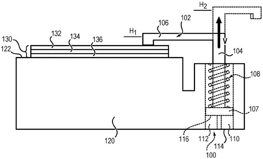
[0050] figure 1 A clamping cylinder 100 according to the invention is shown. As already explained, said clamping cylinders can be used in many applications and in different environments, even though an application of particular relevance to the Applicant is that in the field of energy storage, including in particular energy storage elements (in particular anodes, electrolytes and cathodes, The anode and cathode are equipped with stacks of different thin films of current collectors). The different films are actually stacked on the support and once stacked are moved to another station of the assembly chain, for example enclosing the stack in a mechanical cover. For this operation, at least one clamping cylinder according to the invention is used, which clamps the different stacked films during transport in order to hold the stack in such a way that each layer is not displaced relative to each other and does not Will be displaced relative to the support until after reaching the...


PUM


Abstract

The invention relates to a clamping cylinder (100) comprising a body (110) and a movable assembly (102) contained in a receiving chamber (112) of the body, rotatable and translatable relative to the body along a predetermined movement axis (V), the cylinder comprising guide means (142; 150) in order to guide the movable assembly between a clamping position and a free position. The guide means comprise: - at least one cylindrical roller (150A-150D) arranged on the body of the cylinder such that the axis of the roller is essentially perpendicular to the movement axis (V), - a rod (104) of the movable assembly extending along the movement axis and being configured so as to comprise at least one movement portion (142) having a polygonal section in a plane normal to the movement axis, the section comprising at least one rectilinear edge, the movement portion (142) being configured such that said section follows an essentially helical base line around the movement axis over at least a fraction (143) of the portion, the rod (104) and the rollers (150A-150D) being positioned such that a roller is arranged across from each of the sides of the polygonal section.

Description

technical field [0001] The invention relates to a rotary linear clamping cylinder for clamping components on a support. Background technique [0002] Clamping cylinders generally comprise an L-shaped moving assembly having a vertical rod and a horizontal arm located at the upper end of the rod and integral with the rod. The rod is arranged in the body and is movable in translation and in rotation relative to the body, so that the moving assembly can assume at least two positions relative to the horizontal support, in particular a clamped position and a released position, in the clamped position said arm is disposed above a support adjacent the cylinder at a first height so as to clamp the element to the support, and in said released position the end of said arm is at a second height higher than the first height Set at a certain distance from the support. [0003] The cylinder can be used in many applications, such as a method of manufacturing a battery comprising a plurali...

Claims


Application Information

Patent Timeline
Patent Type & Authority Applications(China)
IPC IPC(8): F15B15/06B25B5/06H01M10/04
CPCB25B5/062F15B15/063H01M10/0404H01M10/0468Y02E60/10Y02P70/50
Inventor G·勒加尔
Owner BLUE SOLUTIONS
Why Eureka
Try Eureka