Porous negative pressure cooling structure for dental handpieces

A technology of dental handpiece and cooling structure, which is applied in the fields of dental drilling, dentistry, medical science, etc. It can solve the problems of inadequate cooling, structural limitations, and actual operation of water outlet blockage, so as to ensure the cooling effect, prevent water and air leakage, Good sealing effect

Active Publication Date: 2018-06-22
SINOL MEDICAL EQUIP GRP CO LTD
View PDF6 Cites 0 Cited by
  • Summary
  • Abstract
  • Description
  • Claims
  • Application Information

AI Technical Summary

Problems solved by technology

Due to structural limitations, single-point cooling often has insufficient cooling and blocked water outlets, and there are many inconveniences in actual operation; although multi-point cooling has certain advantages over single-point cooling, the direction of the water flow channel is basically consistent with the direction of the bur. That is to say, the water needs to flow down to cool the bur, and the water flow that relies on gravity to flow down, once the air pressure in the air channel is too high, when the water and air mix in the head, the air pressure will easily push the water back and cannot form water mist. Even water does not come out; and when the air pressure in the air channel is too small, water mist cannot be formed; in addition, the existing dental handpieces usually affect the normal work of the handpiece due to debris blocking the water outlet, which may occur during the treatment of patients. If the cooling abnormality cannot be repaired in time, it will bring pain to the patient and even cause serious medical accidents, so an improvement is proposed

Method used


Image

  • Porous negative pressure cooling structure for dental handpieces
  • Porous negative pressure cooling structure for dental handpieces
  • Porous negative pressure cooling structure for dental handpieces

Examples


Embodiment Construction

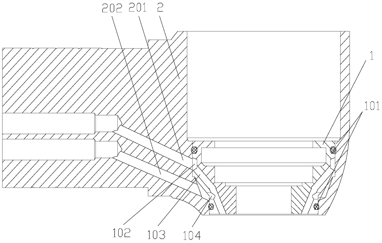
[0018] Attached below Figure 1-4 An embodiment of the present invention is described.

[0019] The porous negative pressure cooling structure for the dental handpiece has a spray seat 1 which is a hollow cylindrical member, and the spray seat 1 is adapted to the head shell 2 and fixed in the head shell 2 at the end of the handle of the dental handpiece. Specifically, the small end of the spray seat 1 is placed inside the nose shell 2 and pressed tightly, so that the lower end surface of the spray seat 1 is aligned with the lower end surface of the nose shell, and the gap between the head shell 2 and the end surface of the spray seat 1 is sealed with glue. .

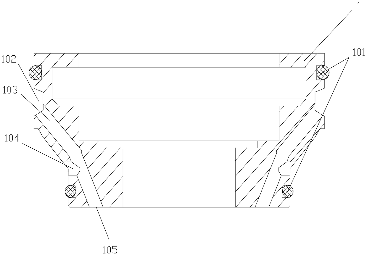
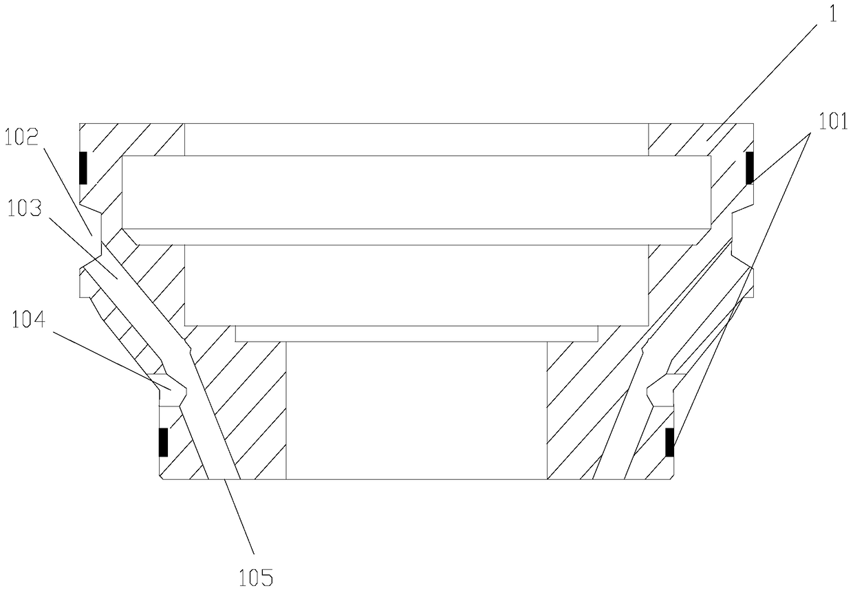
[0020] Both the upper end and the outer wall of the lower end of the spray seat 1 are formed with annular grooves 101 for water and air sealing, in order to achieve a better sealing effect and prevent water and air leakage. Specifically (such as figure 2 As shown), the O-shaped rubber ring is nested in the annular gr...


PUM


Abstract

The invention provides a porous negative pressure type cooling structure used for a dental handpiece. The porous negative pressure type cooling structure used for the dental handpiece comprises a mist spraying base, wherein the mist spraying base is arranged in a nose shell arranged at the end part of a handle of the dental handpiece and is matched with the nose shell, annular grooves used for steam sealing are respectively formed in the outer walls of the two ends of the mist spraying base, a ring-shaped groove is formed below the annular groove arranged at the upper end, one end of the ring-shaped groove is communicated with an air hole formed inside the nose shell to form a ring-shaped air channel, and multiple air channels leading to the lower end face of the mist spraying base are uniformly formed inside the other end of the ring-shaped groove; and multiple water channels are formed above the annular groove arranged at the lower end, one end of each water channel is communicated with a water inlet hole formed inside the nose shell, and the other ends of the water channels run through the air channels in angles. The porous negative pressure type cooling structure used for the dental handpiece has the advantages that a negative pressure principle is utilized for taking water out by virtue of the air, water mist is formed, the aim of cooling is achieved, cooling effect is greatly improved, safe usage rate of the dental handpiece is improved, and service life of the dental handpiece is prolonged.

Description

technical field [0001] The invention belongs to the technical field of oral medical devices, and in particular relates to a porous negative pressure cooling structure for a dental handpiece. Background technique [0002] The dental handpiece is a commonly used medical device in the department of stomatology. Its working principle is to use the air compressor to compress the air into high-pressure gas to blow the turbine to drive the bur to run at a high speed. The speed is usually about 360,000 revolutions per minute. Cutting teeth to remove bad tissue, or preparing porcelain teeth, can also be used for oral treatment such as grinding dentures. In order to prevent handpiece burs from aging due to high-speed grinding and medical accidents, it is necessary to cool the burs in time. Existing dental handpieces can be divided into single-point cooling and multi-point cooling according to their cooling methods. The single-point cooling form is to draw a stream of water from the n...

Claims


Application Information

Patent Timeline
Patent Type & Authority Patents(China)
IPC IPC(8): A61C1/08
CPCA61C1/08A61C2204/00
Inventor 解辽波郭忙强孙建龙
Owner SINOL MEDICAL EQUIP GRP CO LTD
Why Eureka
Try Eureka