A follow-up inkjet equipment
What is Al technical title?
Al technical title is built by PatSnap Al team. It summarizes the technical point description of the patent document.
A follow-up, coding technology, applied in printing, typewriters, etc., can solve problems such as waste of manual labor, misalignment of information printing positions, etc., and achieve the effects of reducing noise, avoiding motion interference, and improving rigidity
Inactive Publication Date: 2016-06-08
SHANDONG JIANZHU UNIV
View PDF4 Cites 0 Cited by
Summary
Abstract
Description
Claims
Application Information
AI Technical Summary
This helps you quickly interpret patents by identifying the three key elements:
Problems solved by technology
Method used
Benefits of technology
Problems solved by technology
However, due to the injection molding production method adopted by the plastic tube, it often causes a certain rotation of the plastic tube when it is extruded from the injection molding machine, so that the position of the information printing is misaligned. of manual labor waste
Method used
Image
Click on the blue label to locate the original text in one second.
Reading with bidirectional positioning of images and text.
Examples
Embodiment Construction
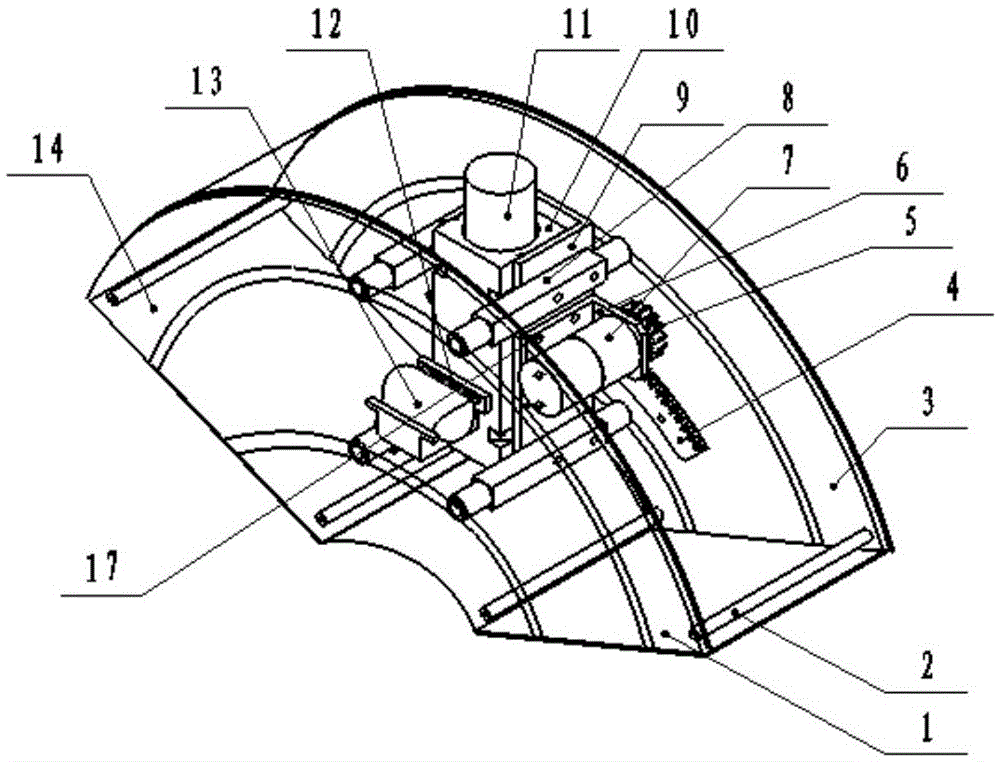
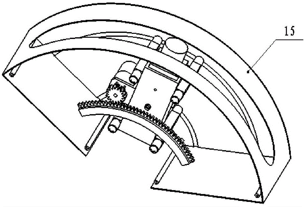
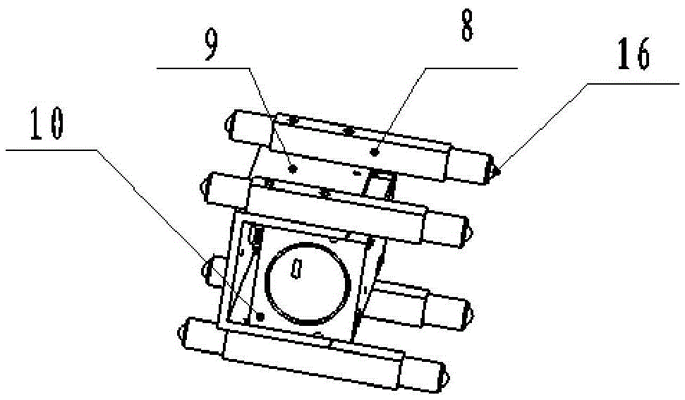
[0016] A follow-up type coding equipment is composed of a rib 1, a support column 2, a rear arc surface 3, a tooth arc 4, a gear 5, a motor mounting plate 6, a DC deceleration motor 7, a roller support column 8, and a coding assembly Set 9, code spraying set 10, spraying terminal 11, CCD bracket 12, CCD13, front arc surface 14, upper cover plate 15 and roller 16, characterized in that: each side of the equipment has a rib 1, two blocks The side surfaces of the limit 1 are respectively equipped with a back arc 3 and a front arc 14, four support columns 2 are installed between the front arc 14 and the back arc 3, and upper arcs 14 and the back arc 3 are equipped with upper The cover plate 15, the tooth arc 4 is installed on the inner side of the rear arc surface 3, and the inner sides of the rear arc surface 3 and the front arc surface 14 are provided with arc-shaped roller grooves 302, and four rollers with rollers 16 are installed. The support column 8 is installed on the codi...
PUM
Abstract
The invention discloses a following type ink jet printing device, and belongs to the field of industrial automation devices. The following type ink jet printing device is composed of stopping edges, supporting columns, a back arc face, a gear arc, a gear, a motor installation plate, a direct-current gear motor, roller supporting columns, an ink jet printing assembly sleeve, an ink jet printing sleeve, an ink jet printing head, a CCD support, a CCD, a front arc face, an upper cover plate and rollers. The following type ink jet printing device is characterized in that the two stopping edges are arranged in the device, the back arc face and the front arc face are installed on the lateral sides of the two stopping edges, the supporting columns are installed between the front arc face and the back arc face, and the upper cover plate is installed on the front arc face and the back arc face; the gear arc is installed on the inner side of the back arc face, the four roller supporting columns are installed on the ink jet printing assembly sleeve, the ink jet printing sleeve is installed in the cold jetting assembly sleeve, the ink jet printing head is installed in the ink jet printing sleeve, the motor installation plate is installed on the ink jet printing assembly sleeve, the direct-current gear motor is installed on the motor installation plate, and the gear is installed on the motor and meshed with the gear arc; and the CCD support is installed on the lateral side of the ink jet printing sleeve, and the CCD is installed on the CCD support. By means of the following type ink jet printing device, product information can be printed to the proper position of a plastic pipe in a jetted manner.
Description
technical field [0001] The invention relates to a follow-up coding equipment, in particular, it adopts machine vision position detection and control feedback, which can make the characters sprayed out of the jetting jet printed on the specified position of the plastic tube. Equipment belongs to the field of industrial automation equipment. Background technique [0002] Plastic pipe is a kind of pipeline commonly used in people's production and life. For the sake of appearance, plastic pipe producers often spray-print product information on the outer surface of the plastic pipe with a spray jet. At present, most plastic pipes are injected with two red and blue parallel stripes along the pipeline axis for aesthetics, and the information is printed in the middle of the stripes. However, due to the injection molding production method adopted by the plastic tube, it often causes a certain rotation of the plastic tube when it is extruded from the injection molding machine, so tha...
Claims
Application Information
Patent Timeline
Application Date:The date an application was filed.
Publication Date:The date a patent or application was officially published.
First Publication Date:The earliest publication date of a patent with the same application number.
Issue Date:Publication date of the patent grant document.
PCT Entry Date:The Entry date of PCT National Phase.
Estimated Expiry Date:The statutory expiry date of a patent right according to the Patent Law, and it is the longest term of protection that the patent right can achieve without the termination of the patent right due to other reasons(Term extension factor has been taken into account ).
Invalid Date:Actual expiry date is based on effective date or publication date of legal transaction data of invalid patent.