
Vertical take-off and landing unmanned aerial vehicle

A technology for vertical take-off and landing of drones, applied in the field of drones, which can solve problems such as slow horizontal flight speed, and achieve the effect of improving stability

Inactive Publication Date: 2016-02-24
上海圣尧智能科技有限公司
View PDF4 Cites 3 Cited by
  • Summary
  • Abstract
  • Description
  • Claims
  • Application Information

AI Technical Summary

Problems solved by technology

However, since the engine cannot generate lift perpendicular to the axis of the fuselage, the fixed-wing UAV can only obtain lift through the relative motion between the fixed wing and the air, so as to overcome the gravity of the fixed-wing UAV, the size of the lift and the fixed-wing There is a positive correlation with the relative speed of motion between the air, the greater the relative motion speed, the greater the lift obtained by the fixed-wing UAV
In the prior art, there are two disadvantages in the fixed-wing UAV: ​​first, a long runway is needed to enable the fixed-wing UAV to obtain sufficient horizontal speed so that the fixed-wing UAV can obtain sufficient lift. Take off; Second, the fixed-wing UAV needs to maintain a sufficient flight speed after take-off in order to obtain enough lift to overcome its own gravity
However, since the rotary wing mainly provides lift, the horizontal thrust parallel to the axis of the fuselage obtained by the rotary wing UAV is relatively small, so the horizontal flight speed is relatively slow.
[0006] To sum up, in the prior art, UAVs either need to rely on long runways, and need to maintain sufficient flight speed after take-off; or the horizontal flight speed is relatively slow

Method used


Image

  • Vertical take-off and landing unmanned aerial vehicle
  • Vertical take-off and landing unmanned aerial vehicle
  • Vertical take-off and landing unmanned aerial vehicle

Examples


Embodiment Construction

[0030] In the prior art, unmanned aerial vehicles either need to rely on long runways, and need to maintain sufficient horizontal flight speed after take-off; or the horizontal flight speed is relatively slow.

[0031] In order to make the above objects, features and advantages of the present invention more comprehensible, specific embodiments of the present invention will be described in detail below in conjunction with the accompanying drawings.

[0032] Compared with fixed-wing drones, vertical take-off and landing drones can take off and land at zero speed, have the ability to hover, and can fly horizontally in the way of fixed-wing flight. Vertical take-off and landing drones are independent of runways and have the advantage of being able to hover.

[0033] VTOL UAVs have much higher forward flight speeds and greater range than rotary-wing UAVs.

[0034] Based on these advantages, vertical take-off and landing drones are especially suitable for occasions that require hov...


PUM


Abstract

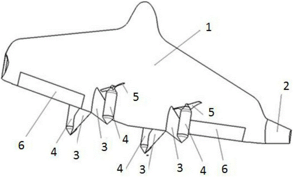
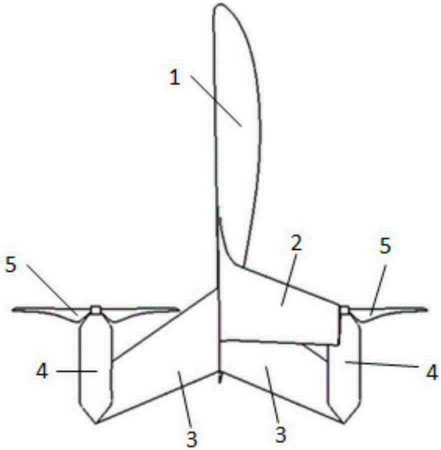
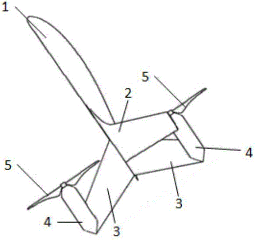
The invention provides a vertical take-off and landing unmanned aerial vehicle. The vertical take-off and landing unmanned aerial vehicle comprises a vehicle body, wings, ailerons, three or more vertical fins, motors and propellers. The ailerons are hinged to the wings. At least one vertical fin is arranged on the upper side of the vertical take-off and landing unmanned aerial vehicle, and at least one vertical fin is arranged on the lower side of the vertical take-off and landing unmanned aerial vehicle. The motors are connected with the vertical fins and comprise motor bearings. At least parts of the trailing edges of the vertical fins are located on the rear portions of the trailing edges of the wings, or the tails of the motors are located on the rear portions of the trailing edges of the wings. The propellers are connected with the motor bearings. When the vertical take-off and landing unmanned aerial vehicle is vertically placed, the vertical fins or the tails of the motors can serve as undercarriages. The vertical take-off and landing unmanned aerial vehicle vertically takes off or lands or hovers in upper air through rotation of the ailerons, and can also achieve a high-speed horizontal flight. Stability is improved through connection of the motors and the vertical fins.

Description

technical field [0001] The invention relates to an unmanned aerial vehicle, in particular to a vertical take-off and landing unmanned aerial vehicle. Background technique [0002] Due to the advantages of small size and low cost of unmanned aerial vehicles, and with the rapid development of flight control technology, communication technology and electronic technology, the performance and types of unmanned aerial vehicles are constantly increasing, making them widely used in military and civilian fields. application requirements are constantly increasing. [0003] UAVs are generally divided into fixed-wing UAVs and rotary-wing UAVs. [0004] Among them, the fixed-wing UAV is driven by the engine, which generates horizontal thrust parallel to the axis of the fuselage, so that the UAV can fly at high speed in the air. However, since the engine cannot generate lift perpendicular to the axis of the fuselage, the fixed-wing UAV can only obtain lift through the relative motion be...

Claims


Application Information

Patent Timeline
IPC IPC(8): B64D27/24B64C9/20B64C25/66
Inventor 张杰
Owner 上海圣尧智能科技有限公司
Learn More