
Automatic pump pressure type toothpaste package bottle

一种自动泵、包装瓶的技术,应用在牙膏包装瓶领域,能够解决活塞不能及时上移、弹性体固定不好、易发生脱落等问题

Inactive Publication Date: 2016-02-24
SHANGHAI JND PLASTIC PRODS
View PDF2 Cites 10 Cited by
  • Summary
  • Abstract
  • Description
  • Claims
  • Application Information

AI Technical Summary

Problems solved by technology

[0002] With the continuous advancement of technology and society, people have put forward higher requirements for the packaging of various daily necessities, and more and more people require that the packaging of the products used can not only meet the requirements of convenient use but also achieve the appearance of beautiful appearance. Need, toothpaste is as people's daily use toiletries, and its packaging is also constantly improved by people, as the invention patent of publication number CN201619795U discloses a kind of pressure pump type packaging bottle, in the technical scheme of this patent, due to the piston and The airtightness of the cooperation between the bottles will cause the piston to not move up in time and affect the stability of the discharge. Another example is that a negative pressure packaging bottle is disclosed in the invention patent with the publication number CN102502060A. There are also some defects in the technical solution. For example, the connection between the pump body and the bottle body is not firm enough, and it is easy to fall off during the pressing process. Wait, these defects have seriously affected the use effect and product quality

Method used


Image

  • Automatic pump pressure type toothpaste package bottle
  • Automatic pump pressure type toothpaste package bottle
  • Automatic pump pressure type toothpaste package bottle

Examples


Embodiment Construction

[0019] The present invention will be further described below in conjunction with accompanying drawing:

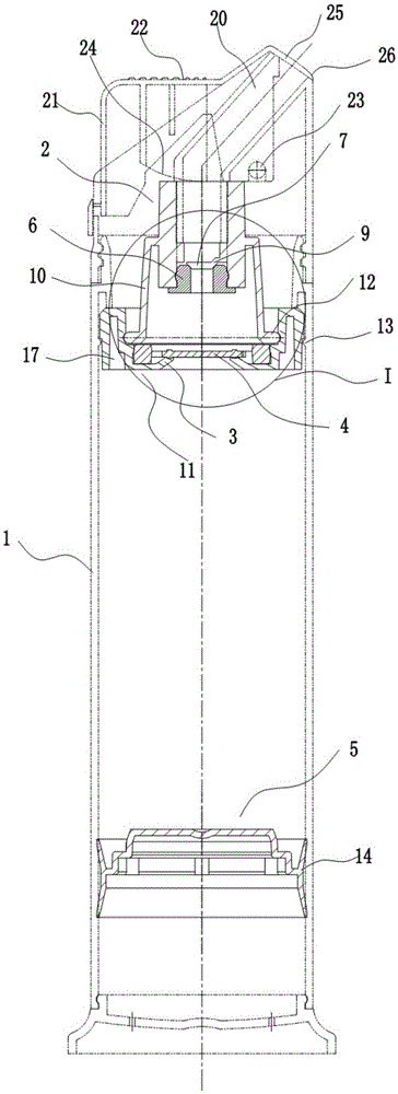
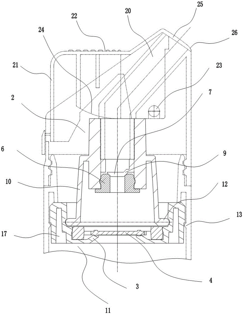
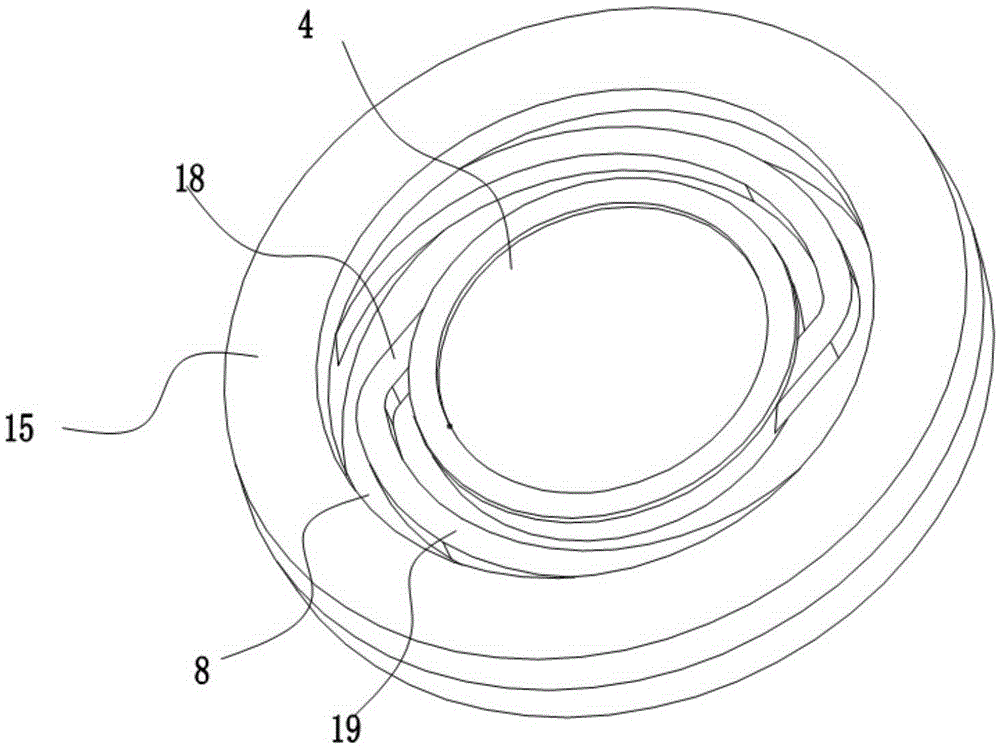
[0020] as attached figure 1 , figure 2 and image 3 As shown, the automatic pumping toothpaste packaging bottle includes a bottle body 1 with an open upper end, and a valve housing 2 whose inner cavity volume can be changed is installed in the bottle body 1, and the upper end and the lower end of the valve housing 2 are respectively provided with There is an opening, and a lower valve seat 3 is provided at the opening of the lower end of the valve housing, and a lower sealing sheet 4 located above the lower valve seat 3 is arranged inside the valve housing 2, and the lower sealing sheet 4 and the lower sealing sheet 4 A sealing pair is provided between the valve seats 3, a connection device is provided between the lower sealing sheet 4 and the valve housing 2, and a cavity for the lower sealing sheet to open upward is provided in the valve housing 2 , the upper opening ...


PUM


Abstract

The invention provides an automatic pump pressure type toothpaste package bottle which comprises a bottle body. A valve shell is mounted in the bottle body. The upper end and the lower end of the valve shell are each provided with an opening. A lower valve seat is arranged at the opening in the lower end of the valve shell. A lower sealing piece is arranged in the valve shell and located on the lower valve seat. A sealing pair is arranged between the lower sealing piece and the lower valve seat. An upper valve seat is arranged at the opening in the upper end of the valve shell. An upper sealing piece is arranged in the valve shell and located on the upper valve seat. A sealing pair is also arranged between the upper sealing piece and the upper valve seat. A piston is further arranged in the bottle body and located below the valve shell. When the valve shell is squeezed, the volume of an inner cavity of the valve shell is decreased, toothpaste between the upper sealing piece and the lower sealing piece is pushed upwards to open the upper sealing piece, and the toothpaste is squeezed out from the upper valve seat. When the squeezing force to the valve shell is canceled, the volume of the inner cavity of the valve shell is increased, so that negative pressure is formed, the toothpaste between the lower sealing piece and the piston is pushed upwards to open the lower sealing piece at the moment, automatic discharging is realized, fragrance leakage can be effectively avoided, and the piston is stably mounted.

Description

technical field [0001] The invention relates to a toothpaste packaging bottle. Background technique [0002] With the continuous advancement of technology and society, people have put forward higher requirements for the packaging of various daily necessities, and more and more people require that the packaging of the products used can not only meet the requirements of convenient use but also achieve the appearance of beautiful appearance. Need, toothpaste is as people's daily use toiletries, and its packaging is also constantly improved by people, as the invention patent of publication number CN201619795U discloses a kind of pressure pump type packaging bottle, in the technical scheme of this patent, due to the piston and The airtightness of the cooperation between the bottles will cause the piston to not move up in time and affect the stability of the discharge. Another example is that a negative pressure packaging bottle is disclosed in the invention patent with the public...

Claims


Application Information

Patent Timeline
Patent Type & Authority Applications(China)
IPC IPC(8): B65D35/48B65D35/50B65D35/30
CPCB65D35/30B65D35/46B65D83/0033B05B11/1029B05B11/1028B05B11/028B05B11/1053B05B11/1069B65D41/005B65D53/04B65D83/0005B65D1/0261B65D47/00
Inventor 黄益新杨锦洪
Owner SHANGHAI JND PLASTIC PRODS
Learn More