Industrial oil smoke anti-pollution discharge equipment

An anti-pollution and oil fume technology, which is used in the removal of oil fume, lighting and heating equipment, and household heating, etc., can solve the problems of oil fume pollution and poor smoke exhaust.

Inactive Publication Date: 2021-11-19
杨菲菲
View PDF7 Cites 0 Cited by
  • Summary
  • Abstract
  • Description
  • Claims
  • Application Information

AI Technical Summary

Problems solved by technology

[0004] In order to overcome the disadvantages of poor smoke exhaust and polluted oil fume of existing smoke exhaust machines, the technical problem to be solved is: to provide an industrial oil fume pollution prevention and discharge equipment that can realize smooth smoke exhaust and improve the quality of smoke exhaust

Method used


Image

  • Industrial oil smoke anti-pollution discharge equipment
  • Industrial oil smoke anti-pollution discharge equipment
  • Industrial oil smoke anti-pollution discharge equipment

Examples


Embodiment 1

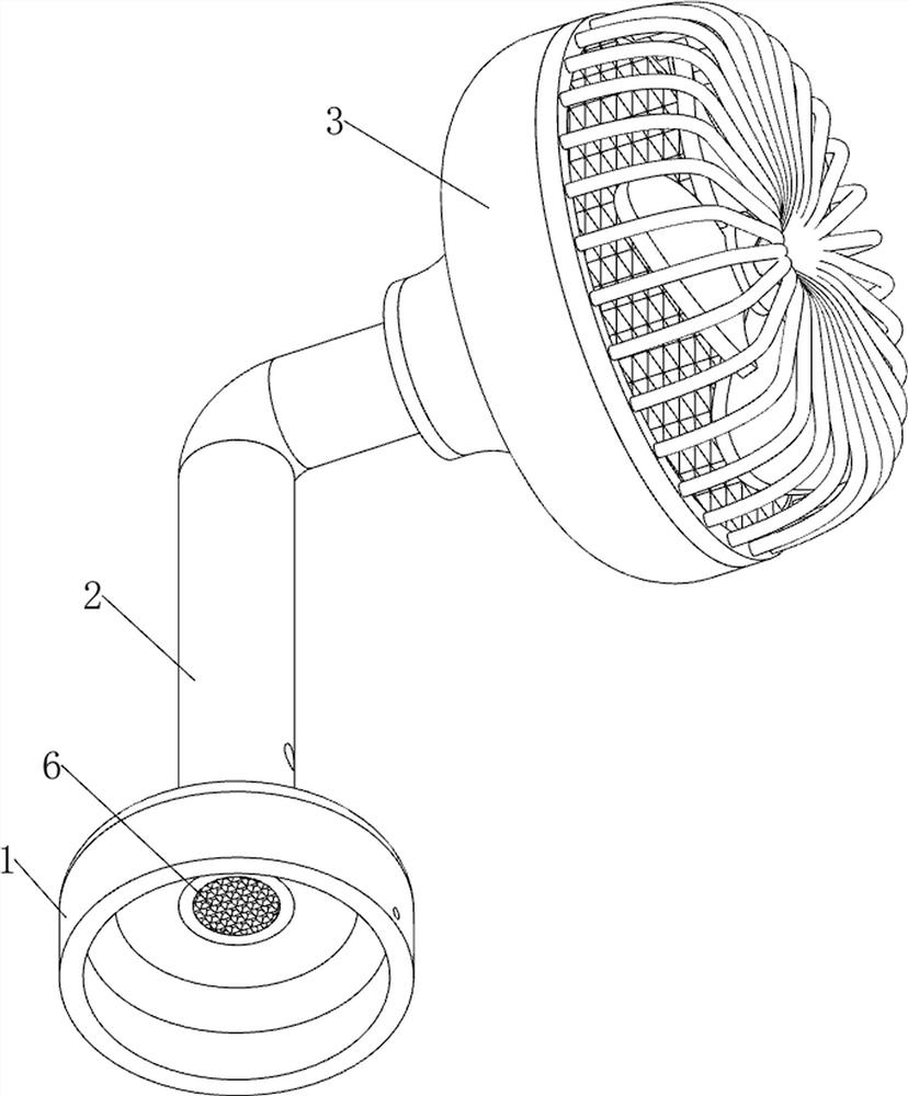
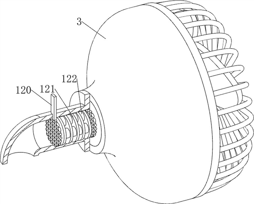
[0025] A kind of industrial oil fume anti-pollution discharge equipment, such as Figure 1-3 As shown, it includes a base 1, an exhaust pipe 2, a protective cover 3, a first turbofan 4, a first filter 5, a second filter 6, a fixing mechanism 7 and a driving mechanism 8, and the top of the base 1 is provided with an exhaust Pipe 2, the right side of the upper part of the exhaust pipe 2 is provided with a protective cover 3, the first turbofan 4 is rotatably connected in the protective cover 3, the left side of the protective cover 3 is provided with a first filter screen 5, the bottom of the exhaust pipe 2 and The upper right side is provided with a second filter screen 6 , the base 1 is provided with a fixing mechanism 7 , and the base 1 is provided with a driving mechanism 8 .

[0026] Fixing mechanism 7 comprises fixed plate 70, slide block 71, first spring 72, nut 73 and bolt 74, and base 1 three sides are all provided with fixed plate 70, and all sliding type is connected ...

Embodiment 2

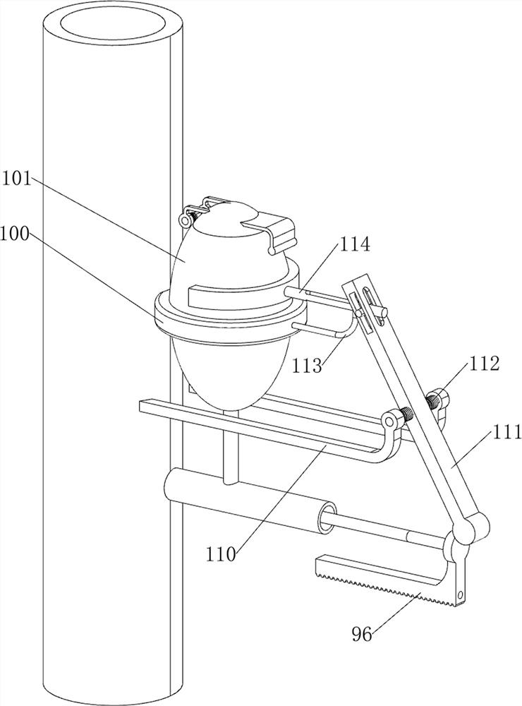
[0030] On the basis of Example 1, such as Figure 4-7 Shown, also include spraying mechanism 9, spraying mechanism 9 includes second bevel gear 90, transmission assembly 91, spur gear 92, guide rod 93, rack 94, rubber rod 95, spray nozzle 96 and second spring 97, install The left side of the lower part of the plate 80 is rotatably connected with a second bevel gear 90, the left front side of the top of the mounting plate 80 is rotatably connected with a spur gear 92, and a transmission assembly 91 is connected between the spur gear 92 and the second bevel gear 90, and the transmission assembly 91 consists of Composed of two pulleys and a belt, the two pulleys are respectively connected to the spur gear 92 and the second bevel gear 90, the belt is wound between the spur gear 92 and the second bevel gear 90, and the lower right side of the exhaust pipe 2 is provided with a guide Rod 93, the guide rod 93 is slidingly connected with a rack 94, the left side of the rack 94 and the ...


PUM


Abstract

The invention relates to discharge equipment, and especially relates to industrial oil smoke anti-pollution discharge equipment. The technical problem to be solved is to provide the industrial oil smoke anti-pollution discharge equipment which can realize smooth smoke discharge and improve the smoke discharge quality. According to the technical scheme, the industrial oil smoke anti-pollution emission equipment comprises a base, an exhaust pipe, a protective cover, a first turbofan, a first filter screen, a second filter screen and a fixing mechanism, the exhaust pipe is arranged at the top of the base, the protective cover is arranged on one side of the upper portion of the exhaust pipe, the first turbofan is rotationally connected into the protective cover, and the first filter screen is arranged on one side in the protective cover; and second filter screens are arranged at the bottom and on one side of the exhaust pipe, and the fixing mechanism is arranged on the base. Through cooperation of the fixing mechanism and the driving mechanism, the equipment can be fixed to the position where oil fume needs to be discharged, and meanwhile the effects of automatically filtering the oil fume and finally discharging the oil smoke can be achieved.

Description

technical field [0001] The invention relates to a discharge device, in particular to an industrial oil fume anti-pollution discharge device. Background technique [0002] With the improvement of people's living standards, people are constantly pursuing the comfort of living in high-rise buildings. When cooking and cooking at home, in order to avoid the indoor air pollution caused by oily fumes, range hoods are generally used to suck away the oily fumes, and then the high-temperature oily fumes are blown away. Piping vents to the outside. [0003] Although this method can temporarily prevent the kitchen and other indoors from being polluted by oily fume, the oily fume will still pollute the outdoor air after it is transferred from the indoor to the outdoor. At present, it is generally a range hood for each family, and then share the exhaust pipe at the same time. The ventilation volume of the flue is limited. During peak cooking hours, a large amount of oily fume emitted by ...

Claims


Application Information

Patent Timeline
Patent Type & Authority Applications(China)
IPC IPC(8): B01D46/00B01D46/10B01D46/30B01D53/78F24C15/20
CPCB01D46/0036B01D46/10B01D46/30B01D53/04B01D53/78F24C15/20F24C15/2035F24C15/2057B01D2253/102B01D2258/0283B01D2258/0275
Inventor 杨菲菲
Owner 杨菲菲
Why Eureka
Try Eureka