Bypass structure, ventilation equipment and ventilation method

A technology of ventilation equipment and bypass channels, applied in mechanical equipment, lighting and heating equipment, heating methods, etc., can solve the problems of large heat exchange core loss, low bypass efficiency, indoor pressure difference, etc., to reduce losses , Reduce energy consumption, reduce cost effect

Active Publication Date: 2018-05-11
GREE ELECTRIC APPLIANCES INC
View PDF6 Cites 0 Cited by
  • Summary
  • Abstract
  • Description
  • Claims
  • Application Information

AI Technical Summary

Problems solved by technology

[0005] The purpose of the present invention is to propose a bypass structure to solve the problem of low bypass efficiency of the bypass structure in the prior art, try to eliminate the pressure difference between the indoor side and the outdoor side, and reduce heat exchange in the ventilation equipment. The loss of the core provides the condition
[0006] Another object of the present invention is to propose a ventilation device and a ventilation method, which can solve the problems of the existing technology that the ventilation equipment will cause a pressure difference between the indoor side and the outdoor side and the loss of the heat exchange core as much as possible.

Method used


Image

  • Bypass structure, ventilation equipment and ventilation method
  • Bypass structure, ventilation equipment and ventilation method
  • Bypass structure, ventilation equipment and ventilation method

Examples


Embodiment Construction

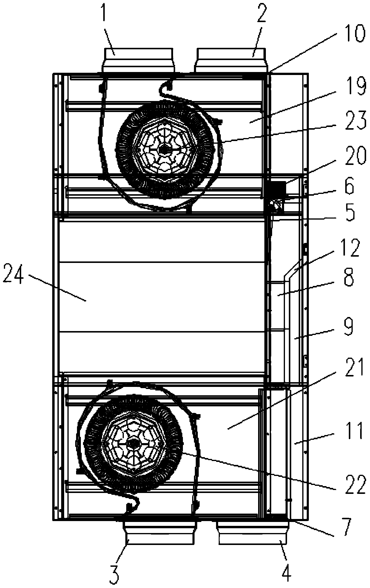
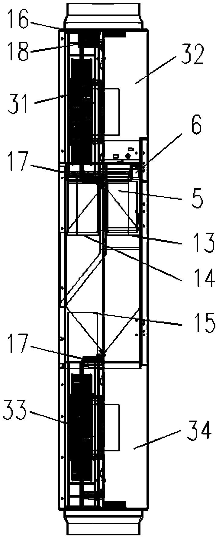
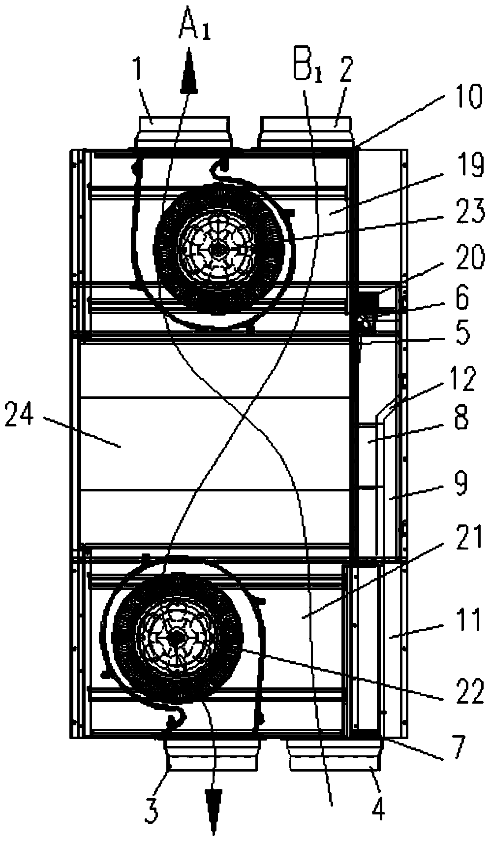
[0044] The technical solutions in the embodiments of the present invention will be clearly and completely described below in conjunction with the drawings in the embodiments of the present invention. Apparently, the described embodiments are only some of the embodiments of the present invention, not all of them. Based on the embodiments of the present invention, all other embodiments obtained by persons of ordinary skill in the art without making creative efforts fall within the protection scope of the present invention.

[0045] In describing the present invention, it should be understood that the terms "center", "transverse", "longitudinal", "front", "rear", "left", "right", "upper", "lower", " The orientations or positional relationships indicated by "vertical", "horizontal", "top", "bottom", "inner" and "outer" are based on the orientations or positional relationships shown in the drawings, and are only for the convenience of describing the present invention and Simplifie...


PUM


Abstract

Disclosed are a bypass structure, a ventilation device, and a ventilation method, wherein the bypass structure is used for the ventilation device. The bypass structure is disposed in parallel with a primary ventilation structure in the ventilation device. The bypass structure comprises a fresh air bypass passage (8) and a discharge air bypass passage (9), which are independent from each other. The fresh air bypass passage (8) is configured to provide a flow passage for outdoor fresh air flowing through the ventilation device from the outdoor side to the indoor side, and the discharge air bypass passage (9) is configured to provide a flow passage for indoor discharge air flowing through the ventilation device from the indoor side to the outdoor side. A first airflow gate (51) is provided in the fresh air bypass passage (8) and a second airflow gate (52) is provided in the discharge air bypass passage (9), for opening or closing the fresh air bypass passage (8) and the discharge air bypass passage (9), respectively. With the bypass structure, the bypass ventilation efficiency is improved, and a pressure difference between the indoor side and the outdoor side can be eliminated, avoiding unfiltered air from directly entering the indoor side and reducing wear and tear of the primary ventilation structure. The ventilation device and method use the bypass structure in ventilation, reducing wear and tear of the primary ventilation structure.

Description

technical field [0001] The invention relates to the technical field of ventilation and ventilation, in particular to a bypass structure, a ventilation device and a ventilation method. Background technique [0002] When the full heat exchange fresh air fan is used in spring and autumn, because the difference between the indoor temperature and the outdoor temperature is small, there is no need to turn on the temperature adjustment equipment indoors. Heat exchange will not only reduce the efficiency of heat exchange, but also reduce the amount of fresh air in the room and increase the energy consumption in the room. [0003] The existing full heat exchange fresh air blower adopts the following method when it is used in spring and autumn (the temperature difference is small): an air passage is set on the indoor air exhaust side air flow passage in the machine, and the air passage is controlled by the air valve. On and off of the channel. The user controls the opening and closi...

Claims


Application Information

Patent Timeline
Patent Type & Authority Patents(China)
IPC IPC(8): F24F7/08F24F11/77F24F11/79F24F13/02F24F13/28F24F13/30F24F110/40F24F110/10
CPCF24F7/08F24F11/30F24F11/89F24F13/02F24F13/28F24F13/30F24F2110/00F24F11/00Y02B30/70
Inventor 杨力杜辉刘煜周洋臧海龙
Owner GREE ELECTRIC APPLIANCES INC
Why Eureka
Try Eureka