Liquid crystal display panel and display device

A technology of liquid crystal display panels and liquid crystals, applied in nonlinear optics, instruments, optics, etc., can solve problems such as good results, and achieve the effects of slowing down speed, improving puncture and liquid crystal pollution

Inactive Publication Date: 2016-02-24
WUHAN CHINA STAR OPTOELECTRONICS TECH CO LTD
View PDF5 Cites 13 Cited by
  • Summary
  • Abstract
  • Description
  • Claims
  • Application Information

AI Technical Summary

Problems solved by technology

Design a groove between the AA area and the frame sealant to slow down the flow of liquid cry

Method used


Image

  • Liquid crystal display panel and display device
  • Liquid crystal display panel and display device
  • Liquid crystal display panel and display device

Examples


Embodiment 1

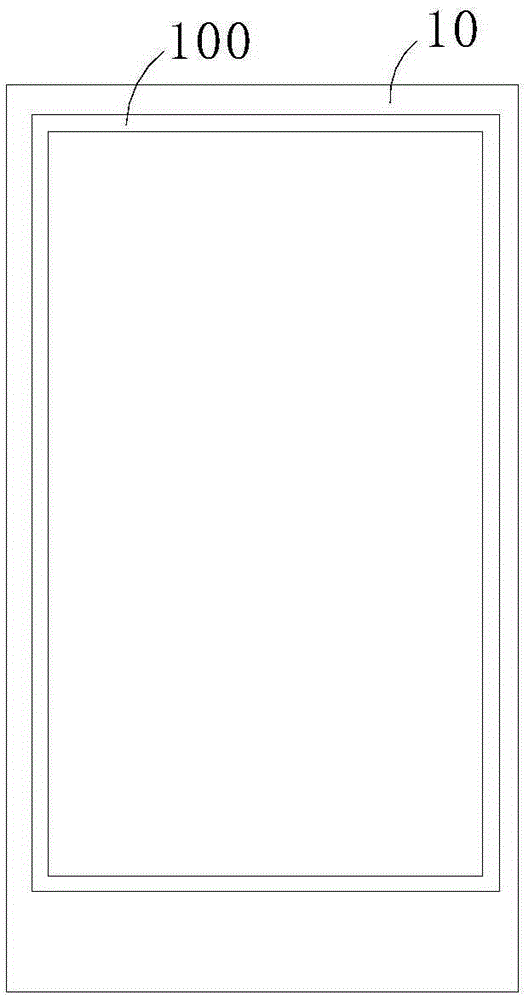
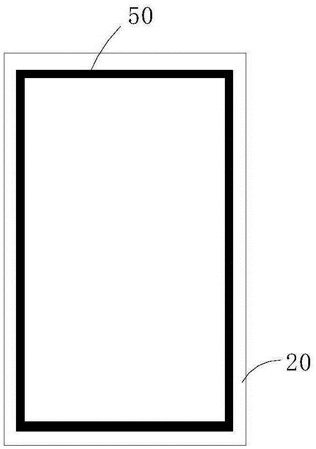
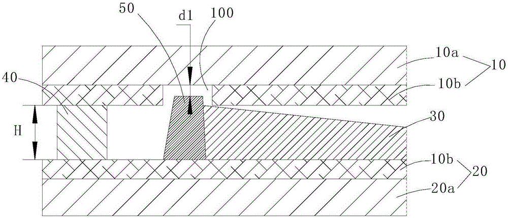
[0031] refer to Figure 1 ~ Figure 3 The liquid crystal display panel of the present invention includes an upper substrate 10, a lower substrate 20, a liquid crystal 30 filled between the upper substrate 10 and the lower substrate 20, a frame 40 forming a closed cavity with the upper substrate 10 and the lower substrate 20, and a frame 40 located in the frame 40 inside, a circle of first spacer retaining wall 50 located on the lower substrate 20, the height of the first spacer retaining wall 50 is higher than the thickness H of the box formed when the upper substrate 10 and the lower substrate 20 are paired, and the second A distance between the end surface of a spacer wall 50 and the inner surface of the upper substrate 10 forms a channel through which the liquid crystal 30 can flow. Here, the frame 40 is a frame-shaped sealant, which is disposed on the edges of the upper substrate 10 and the lower substrate 20 .

[0032] Here, the upper substrate 10 and the lower substrate ...

Embodiment 2

[0040] Such as Figure 7 , different from Embodiment 1, on the basis of it, the upper substrate 10 and / or the lower substrate 20 of this embodiment can also be provided with a columnar spacer column 70, the height of the spacer column 70 is less than the thickness H of the box, preferably the upper The spacer columns 70 on the substrate 10 and the spacer columns 70 on the lower substrate 20 protrude toward the middle alternately, which can block the flow velocity of the liquid crystal 30 to a certain extent, and the effect is more obvious when the number is large.

Embodiment 3

[0042] Such as Figure 8 Different from the above embodiments, the liquid crystal display panel of this embodiment also includes a circle of second spacer retaining walls 60 arranged on the upper substrate 10, and the height of the first spacer retaining walls 60 is higher than that of the upper substrate 10. The thickness H of the cell formed when the cell is aligned with the lower substrate 20 , and the space between the end surface of the second spacer wall 50 and the inner surface of the lower substrate 20 forms a channel through which the liquid crystal 30 can flow.

[0043] An annular second groove 200 is defined on the inner surface of the lower substrate 20 , and the end of the second spacer wall 60 extends into the second groove 200 and maintains a second gap d2 with the bottom surface of the second groove 200 . Wherein, the second spacer retaining wall 60 can also be multi-turn, and the second spacer retaining wall 60 is arranged alternately and at intervals, forming...


PUM


Abstract

The invention discloses a liquid crystal display panel which comprises an upper substrate, a lower substrate, a liquid crystal filled between the upper substrate and the lower substrate, a frame of a closed cavity encircled by the upper substrate and the lower substrate, and a circle of first spacer retaining walls which are positioned on the inner side of the frame and are arranged on the lower substrate, wherein the height of each first spacer retaining wall is higher than the box thickness formed in the process of boxing the upper substrate and the lower substrate; and channels through which the liquid crystal flow are formed between the end surfaces of the first spacer retaining walls and the inner surface of the upper substrate at intervals. The invention also discloses a display device. The speed of allowing the liquid crystal to flow to frame sealing glue can be reduced, the liquid crystal is well prevented from flowing to frame sealing glue before the liquid crystal is filled with the space in the spacer retaining walls, the mode of allowing the liquid crystal to rapidly and comprehensively impacting the frame sealing glue in the horizontal direction is changed into a mode of locally and slowly contacting in the vertical direction, and the problems such as frame sealing glue puncture and liquid crystal pollution are solved. In addition, the problem of non-uniform box thickness is solved.

Description

technical field [0001] The invention relates to the technical field of liquid crystal display, in particular to a liquid crystal display panel and a display device. Background technique [0002] At present, the box alignment process of display panels usually goes through the following steps: First, apply a sealant around the display area of ​​the array substrate, drop liquid crystals in the space surrounded by the sealant, and connect the color filter substrate to the array filled with liquid crystals. The substrate is assembled to the box, and then the sealing glue is pre-cured, and finally the sealing glue is further cured with ultraviolet (UV) to complete the box alignment process. [0003] The ODF (liquid crystal pre-dropping) process is an epoch-making manufacturing method. In the past, it was time-consuming, low yield and difficult to achieve. Using ODF process technology, the problems can be easily solved. Liquid crystal pre-dropping generally refers to using multipl...

Claims


Application Information

Patent Timeline
IPC IPC(8): G02F1/1339G02F1/1341
CPCG02F1/13394G02F1/1341G02F1/13415
Inventor 唐岳军
Owner WUHAN CHINA STAR OPTOELECTRONICS TECH CO LTD
Why Eureka
Try Eureka