Mounting structure for electric motors

A motor and frame technology, applied in the direction of electromechanical devices, electric components, electrical components, etc., can solve the problems of unsuitability for electric motors, increased manufacturing workload, etc., and achieve the effect of increasing operational safety and service life, and improving vibration behavior.

Inactive Publication Date: 2019-03-22
SIEMENS AG
View PDF9 Cites 0 Cited by
  • Summary
  • Abstract
  • Description
  • Claims
  • Application Information

AI Technical Summary

Problems solved by technology

However, this mounting structure leads to increased manufacturing work due to the need for a large number of additional parts, including rubber bushes and fixed bushings, and this mounting structure may not be suitable for larger motors because it allows the motor to rotate in all spatial directions. exercise

Method used


Image

  • Mounting structure for electric motors
  • Mounting structure for electric motors
  • Mounting structure for electric motors

Examples


Embodiment Construction

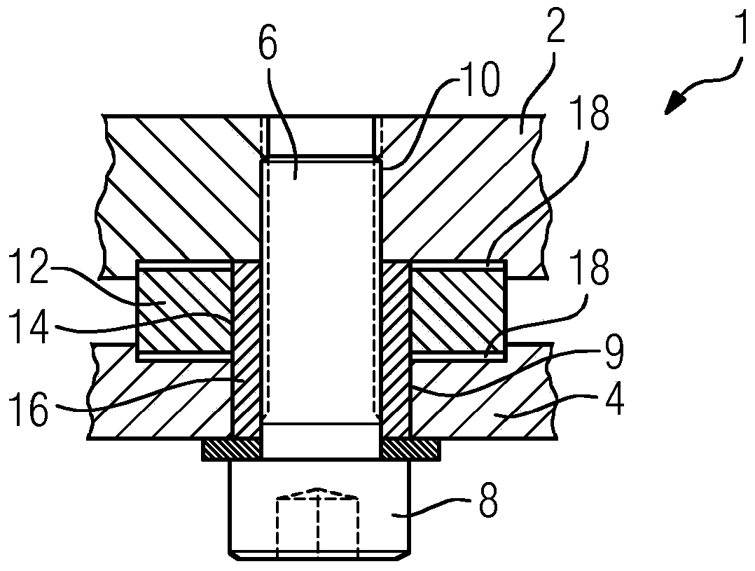
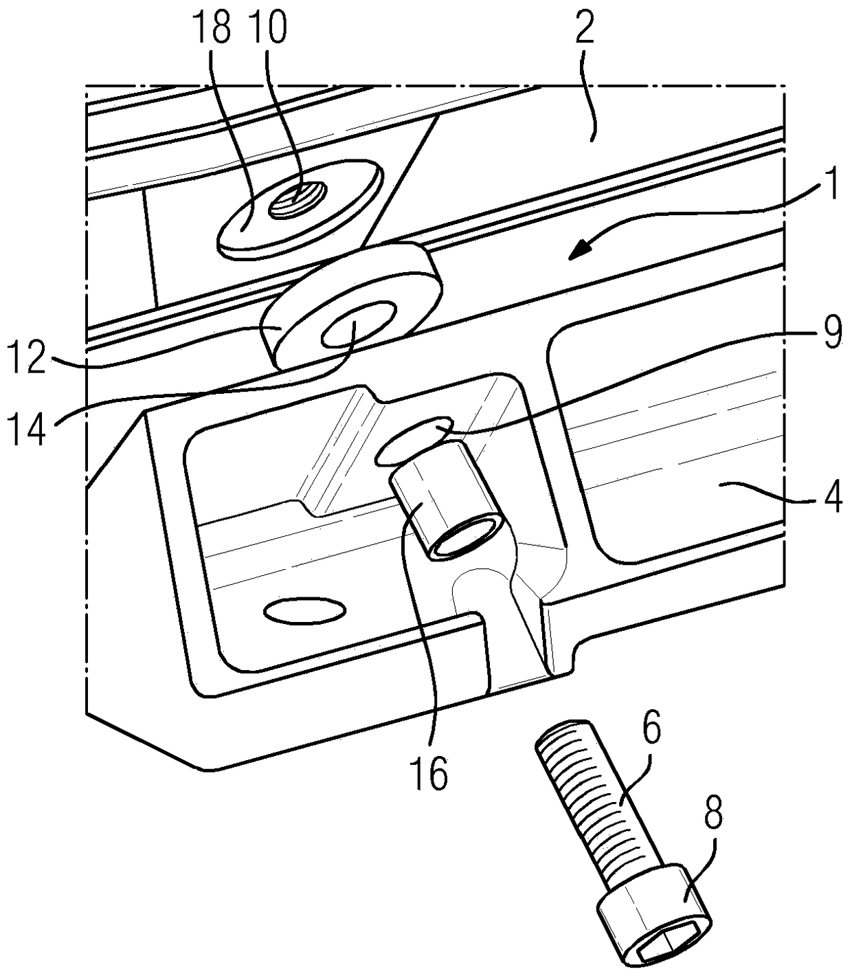
[0025] figure 1 A cross-sectional view of a mounting structure 1 for an electric motor, in particular a squirrel-cage electric motor, is shown. The installation structure 1 connects the fixed frame 2 with the base 4 through screws 6 . The screw 6 has a cylindrical shape and a screw head 8 with a larger diameter than the body of the screw 6 . The body of the screw 6 has an external thread (not shown). The screw 6 penetrates a hole 9 in the base 4 , which has a smaller diameter than the screw head 8 of the screw 6 , and the screw 6 is screwed into a threaded hole 10 in the frame 2 .

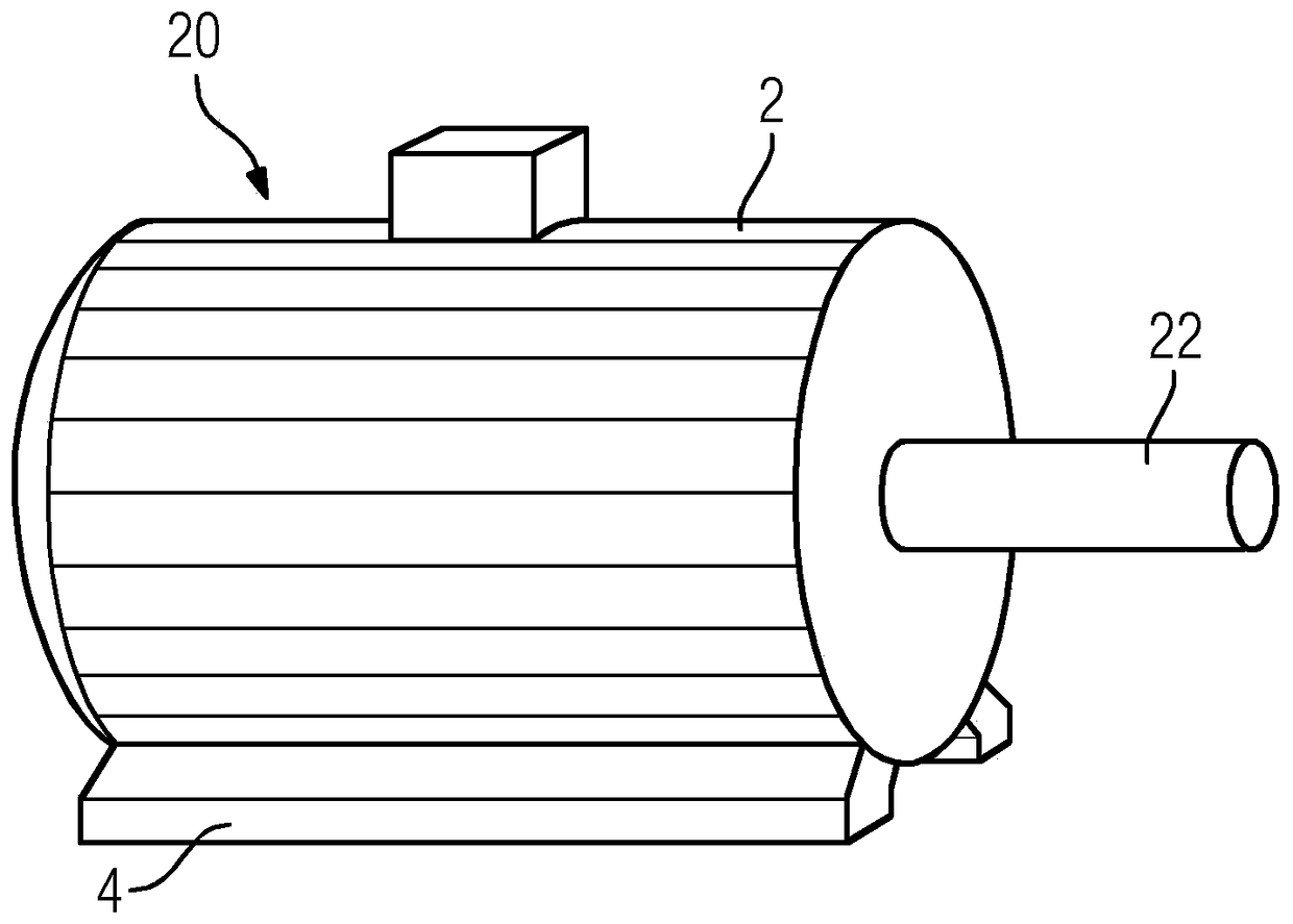
[0026] The general structure of a squirrel cage motor has been described. Owing to the alternating electromagnetic forces, vibrations will occur, especially in squirrel-cage motors with two magnetic poles. In order to reduce these vibrations, a partition 12 made of elastic material is placed between the frame 2 and the base 4 . The elastic material can consist, for example, of rubber.

[0027...


PUM


Abstract

A mounting structure (1) for an electric motor, wherein a frame (2) of the motor is mounted to a foot (4) by means of a screw (6), wherein the screw (6) extends through a hole (14) in a spacer plate (12) situated between the frame (2) and the foot (4), shall allow the mounting of an electric motor with low manufacturing efforts, while at the same time allowing for vibrations to stay within allowable limits. To this end, the spacer plate (12) comprises an elastic material.

Description

technical field [0001] The invention relates to a mounting structure for an electric motor, wherein the frame of the motor is mounted to the base by screws, wherein the screws pass through holes in a partition between the frame and the base, and wherein the partition comprises an elastic material . Background technique [0002] An electric motor is a motor that converts electrical energy into mechanical energy. In normal motor drive mode, most electric motors work by the interaction between the motor's magnetic field and winding currents to generate force within the motor. In certain applications, such as in the industry of transportation by traction motors, the electric motors can be operated in motor drive and generating or braking modes to also generate electrical energy from mechanical energy. [0003] Today, induction motors or asynchronous motors are commonly used. These are alternating current (AC) motors in which all electromagnetic energy is transferred by induct...

Claims


Application Information

Patent Timeline
Patent Type & Authority Patents(China)
IPC IPC(8): F16F15/08H02K5/24
CPCH02K5/24F16F15/08
Inventor 利波尔·瓦夫拉弗拉迪米尔·巴耶尔拉多米尔·拉斯卡亚历山大·韦利茨卡
Owner SIEMENS AG
Why Eureka
Try Eureka