
A method, device, and device for transmitting correlation characteristics between transmit antennas

A technology of transmitting antennas and related characteristics, applied in the field of communication, can solve the problems of reducing the number of service data transmission resources, restricting high-speed data transmission, reducing service data transmission rate, etc., and achieving the effect of reducing transmission overhead.

Active Publication Date: 2018-12-07
HUAWEI TECH CO LTD
View PDF3 Cites 0 Cited by
  • Summary
  • Abstract
  • Description
  • Claims
  • Application Information

AI Technical Summary

Problems solved by technology

Since the number of CSI-RS ports corresponds to the number of transmit antennas, and the CSI-RS resource units used by each antenna port are orthogonal to each other, the resource units occupied by CSI-RS cannot be used to transmit downlink service data. Therefore, in massive MIMO BS In the case of hundreds of antennas on the end, the increase in the number of CSI-RS ports brought about by the increase in the number of transmit antennas will lead to a reduction in the number of resources for service data transmission, thereby reducing the transmission rate of service data
In the case of BS with 32 antennas and 64 antennas, according to the technical scheme of the existing technology, the overhead of CSI-RS will reach 25% and 50%, and the corresponding number of service data resources will be reduced from 34% to 9%, which restricts high Speed ​​Data Transmission

Method used

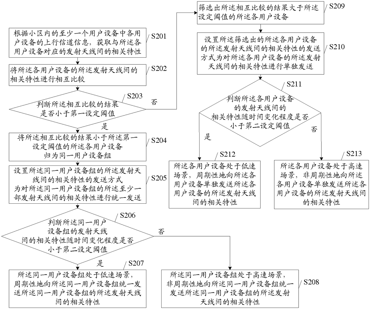
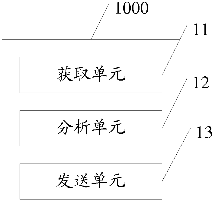

Image

  • A method, device, and device for transmitting correlation characteristics between transmit antennas
  • A method, device, and device for transmitting correlation characteristics between transmit antennas
  • A method, device, and device for transmitting correlation characteristics between transmit antennas

Examples


Embodiment Construction

[0057] The following will clearly and completely describe the technical solutions in the embodiments of the present invention with reference to the accompanying drawings in the embodiments of the present invention. Obviously, the described embodiments are only some, not all, embodiments of the present invention. Based on the embodiments of the present invention, all other embodiments obtained by persons of ordinary skill in the art without creative efforts fall within the protection scope of the present invention.

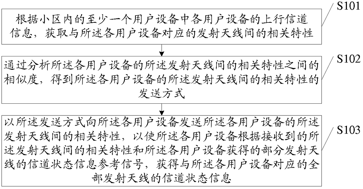
[0058] figure 1 It is a flowchart of an embodiment of a method for transmitting correlation characteristics between transmitting antennas in the present invention. Such as figure 1 As shown, the method includes the following steps:

[0059] Step S101 , according to the uplink channel information of each user equipment in at least one user equipment in a cell, obtain correlation characteristics between transmit antennas corresponding to each user equipment.

[00...


PUM


Abstract

A downlink channel state information transmission method, device, and equipment. The method comprises: obtaining, according to the uplink channel information of each of at least one user equipments in a cell, the relevant attributes of the transmitting antennas corresponding to each user equipment; obtaining, by means of analyzing the degree of similarity between the relevant attributes of the transmitting antennas of each user equipment, the means of transmission of the relevant attributes of the transmitting antennas of each user equipment; using the means of transmission to send to each user equipment the relevant attributes of the transmitting antennas of each user equipment, such that each user equipment obtains, according to the received relevant attributes of the transmitting antennas and the channel state information reference signals, obtained by each user equipment, of some of the transmitting antennas, the channel state information of all of the transmitting antennas corresponding to each user equipment. The technical solution uses the downlink channel state information transmission method, device, and equipment of the present invention to greatly reduce the transmission overhead for downlink channel state information of a large-scale antenna system.

Description

technical field [0001] The present invention relates to the field of communication technologies, and in particular to a method, device and equipment for transmitting correlation characteristics between transmitting antennas. Background technique [0002] With the continuous development of the multi-antenna theory, the multiple input multiple output (Multiple Input Multiple Output, MIMO) wireless communication technology is becoming more and more mature. The more base station (Base Station, BS) / user equipment (User Equipment, UE) antennas, the better the performance in terms of data rate and link reliability. As an emerging technology, massive MIMO (including Large-Scale Antenna Systems, Very Large MIMO, Hyper MIMO, Full-Dimension MIMO and ARGOS) usually uses hundreds of antennas as BS antenna array. Massive MIMO can obtain more degrees of freedom, and increase the capacity by more than 10 times compared with the space division multiplexing of traditional MIMO; a large numb...

Claims


Application Information

Patent Timeline
IPC IPC(8): H04B7/06
CPCH04B7/0665
Inventor 毕晓艳陈大庚盛杰
Owner HUAWEI TECH CO LTD
Learn More