To-be-processed material bin structure for spinning machine

A technology to be processed and spinning machine, applied in the direction of metal processing, metal processing equipment, manufacturing tools, etc., can solve the problems of defective products, decreased production efficiency, increased production costs, etc., to achieve automatic feeding, improve production efficiency, The effect of improving delivery efficiency

Inactive Publication Date: 2016-03-02
SUZHOU SANFU AUTOMATION TECH CO LTD
View PDF7 Cites 2 Cited by
  • Summary
  • Abstract
  • Description
  • Claims
  • Application Information

AI Technical Summary

Problems solved by technology

[0002] At present, when producing the filter in the compressor pipeline of refrigeration equipment, a spinning machine is needed. The technical principle of the spinning machine is to make the point of stress change from point to line and from line to surface by rotating, and at the same time in a certain A certain pressure is given in the direction to make the metal material deform and flow along this direction to form a certain shape. In the actual operation process, it is necessary to carry out feeding and clamping for the spinning machine, but at present, manual feeding is used, and in the upper During the material process, it is easy to process unqualified raw materials and produce defective products, resulting in a decrease in production efficiency and an increase in production costs.

Method used


Image

  • To-be-processed material bin structure for spinning machine
  • To-be-processed material bin structure for spinning machine

Examples


Embodiment Construction

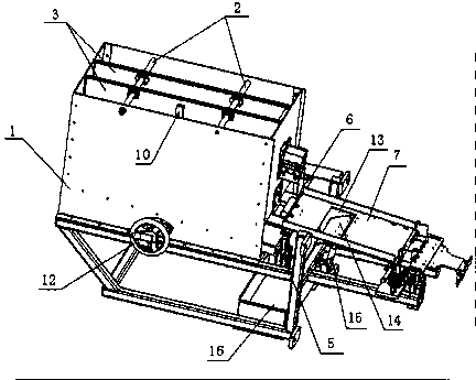
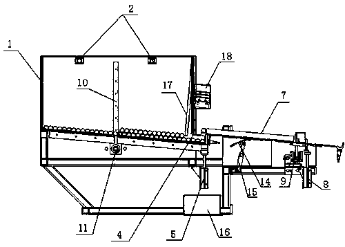
[0012] The present invention will be described in detail below in conjunction with the accompanying drawings.

[0013] Such as figure 1 with figure 2 The material box structure to be processed for a spinning machine shown includes a box body 1, two guide rods 2 arranged in parallel are arranged inside the box body 1, and two guide rods 2 are arranged on the two described guide rods 2. There are two drive limit plates 3 arranged in parallel, and the two drive limit plates 3 are perpendicular to the center line of the guide rod 2. The bottom surface of the box body 1 is inclined, and the bottom surface of the box body 1 is The lower end of the inclination is provided with a discharge port 4, a lift cylinder 5 is provided at the discharge port 4, a detection cylinder 6 is provided beside the lift cylinder 5, and a detection cylinder 6 is provided at the discharge port 4. A bending plate 7 is provided, and the bending plate 7 is inclined, and the inclined high end of the bendin...


PUM


Abstract

The invention relates to a to-be-processed material bin structure for a spinning machine. The to-be-processed material bin structure comprises a bin body, wherein two guide rods are arranged inside the bin body in parallel; two drive limiting plates are arranged on the two guide rods in parallel and are perpendicular to the center lines of the guide rods; the bottom face of the bin body is inclined; a discharge outlet is formed in the low end of the inclined bottom face of the bin body; a lifting air cylinder is arranged at the discharge outlet position; a detection air cylinder is arranged near the lifting air cylinder; an inclined bending plate is arranged at the discharge outlet, the high end of the inclined bending plate is higher than the discharge outlet, and a limiting air cylinder and a centering device are arranged at the low end of the inclined bending plate. By the adoption of the structure, raw materials of multiple specifications can be fed through the drive limiting plates, feeding automation is achieved, and rejected products can be collected after being detected out; the to-be-processed material bin structure is simple in structure and convenient to use; the product feeding efficiency and the production efficiency are improved.

Description

technical field [0001] The invention relates to a material feeding device for the production and manufacture of refrigeration equipment, in particular to a material box structure to be processed for a spinning machine. Background technique [0002] At present, when producing the filter in the compressor pipeline of refrigeration equipment, a spinning machine is needed. The technical principle of the spinning machine is to make the point of stress change from point to line and from line to surface by rotating, and at the same time in a certain A certain pressure is given in the direction to make the metal material deform and flow along this direction to form a certain shape. In the actual operation process, it is necessary to carry out feeding and clamping for the spinning machine, but at present, manual feeding is used, and in the upper During the feeding process, it is easy to process unqualified raw materials and produce defective products, resulting in a decrease in produ...

Claims


Application Information

Patent Timeline
Patent Type & Authority Applications(China)
IPC IPC(8): B21D43/00B21C51/00
CPCB21D43/006B21C51/00
Inventor 武艳阳
Owner SUZHOU SANFU AUTOMATION TECH CO LTD
Why Eureka
Try Eureka