
High-stability steel plate processing device

A processing device and high-stability technology, applied in the field of high-stability steel plate processing devices, can solve the problems of cumbersome operation and physical exertion, and achieve the effect of improving efficiency and saving labor.

Inactive Publication Date: 2016-03-02
四川燚成钢结构有限公司
View PDF6 Cites 3 Cited by
  • Summary
  • Abstract
  • Description
  • Claims
  • Application Information

AI Technical Summary

Problems solved by technology

The so-called manual method is to manually send the thin steel plate to the bottom of the shearing machine for cutting. This method is cumbersome and labor-intensive.

Method used


Image

  • High-stability steel plate processing device

Examples


Embodiment Construction

[0012] The present invention will be further described below in conjunction with accompanying drawing:

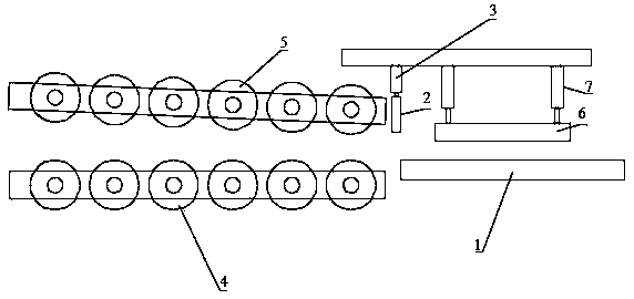
[0013] Such as figure 1 As shown, a high-stability steel plate processing device includes a steel plate conveying device, a working platform 1, a shearing knife 2, and a vertical hydraulic cylinder 3 that drives the shearing knife 2 to move vertically. A plurality of lower feeding rollers 4 distributed and a plurality of upper feeding rollers 5 arranged above the lower feeding rollers, with the conveying direction of the material as the front, the distance between the upper feeding rollers 5 and the lower feeding rollers gradually moves from back to front. reduce, the working platform 1 is flush with the plane where the upper edge of the lower feeding roller is located, and the working platform 1 is located in front of the lower feeding roller, and the shearing knife 2 is arranged above the rear edge of the working platform 1, and the shearing knife 2. Fixedly installed on...


PUM

PropertyMeasurementUnit
thicknessaaaaaaaaaa

Abstract

The invention discloses a high-stability steel plate processing device which comprises a steel plate conveying device, a working platform, a plate cutting knife and a vertical hydraulic cylinder, wherein taking the conveying direction of materials as the front, distances between upper feed rolls and lower feed rolls are gradually reduced from the back to front; the working platform is flush with the plane where the upper edges of the lower feed rolls are located, and is positioned at front of the lower feed rolls; the plate cutting knife is arranged above the rear edge of the working platform, and is fixedly mounted at the end part of a piston rod of the vertical hydraulic cylinder; and a pressure plate for pressing the formed materials and an air cylinder for driving the pressure plate to vertically lift are arranged at the front of the plate cutting knife. The high-stability steel plate processing device has the benefits that the efficiency is improved; the manpower is saved; and smooth leading-in and conveying of plates of different thicknesses can be realized.

Description

technical field [0001] The invention relates to the technical field of steel processing devices, in particular to a high-stability steel plate processing device. Background technique [0002] In daily life, thin steel plates have been used in various fields, such as decoration, construction, machinery and other fields. After the steel plate is stamped and formed, it needs to be cut for easy use and transportation. [0003] In the prior art, in the process of cutting thin steel plates, numerical control equipment or manual separation are generally used. The so-called manual method is to manually send the thin steel plate to the bottom of the shearing machine for cutting. This method is cumbersome and labor-intensive. Contents of the invention [0004] The purpose of the present invention is to overcome the disadvantages of the prior art and provide a cutting device for steel components that improves processing efficiency. [0005] The purpose of the present invention is ...

Claims


Application Information

Patent Timeline
Patent Type & Authority Applications(China)
IPC IPC(8): B21D43/09B21D43/28B23D15/08B23D15/14
CPCB21D43/09B21D43/287B23D15/08B23D15/14
Inventor 李文全
Owner 四川燚成钢结构有限公司
Learn More