
Supporting frame

A technology on a support frame and a support frame, which is applied in the field of support frames, can solve the problems of inconvenient operation for employees, easy dumping of storage boxes, and easy falling on the ground, etc., and achieves the effect of saving space, reliable and stable placement, and high reliability.

Inactive Publication Date: 2016-03-02
GUANGDONG OPPO MOBILE TELECOMM CORP LTD
View PDF10 Cites 1 Cited by
  • Summary
  • Abstract
  • Description
  • Claims
  • Application Information

AI Technical Summary

Problems solved by technology

[0002] The storage boxes used to store products on the production line are usually placed on the ground or on the round stools next to the employees’ operating stations. Static electricity and rubber skins that reduce fatigue from standing, the round stool is not stable, and the storage box placed on the round stool is easy to fall over
[0003] In addition, the storage boxes in the workshop are generally carried manually, which is laborious and easy to fall to the ground, which is unreliable

Method used


Image

  • Supporting frame
  • Supporting frame
  • Supporting frame

Examples


Embodiment 1

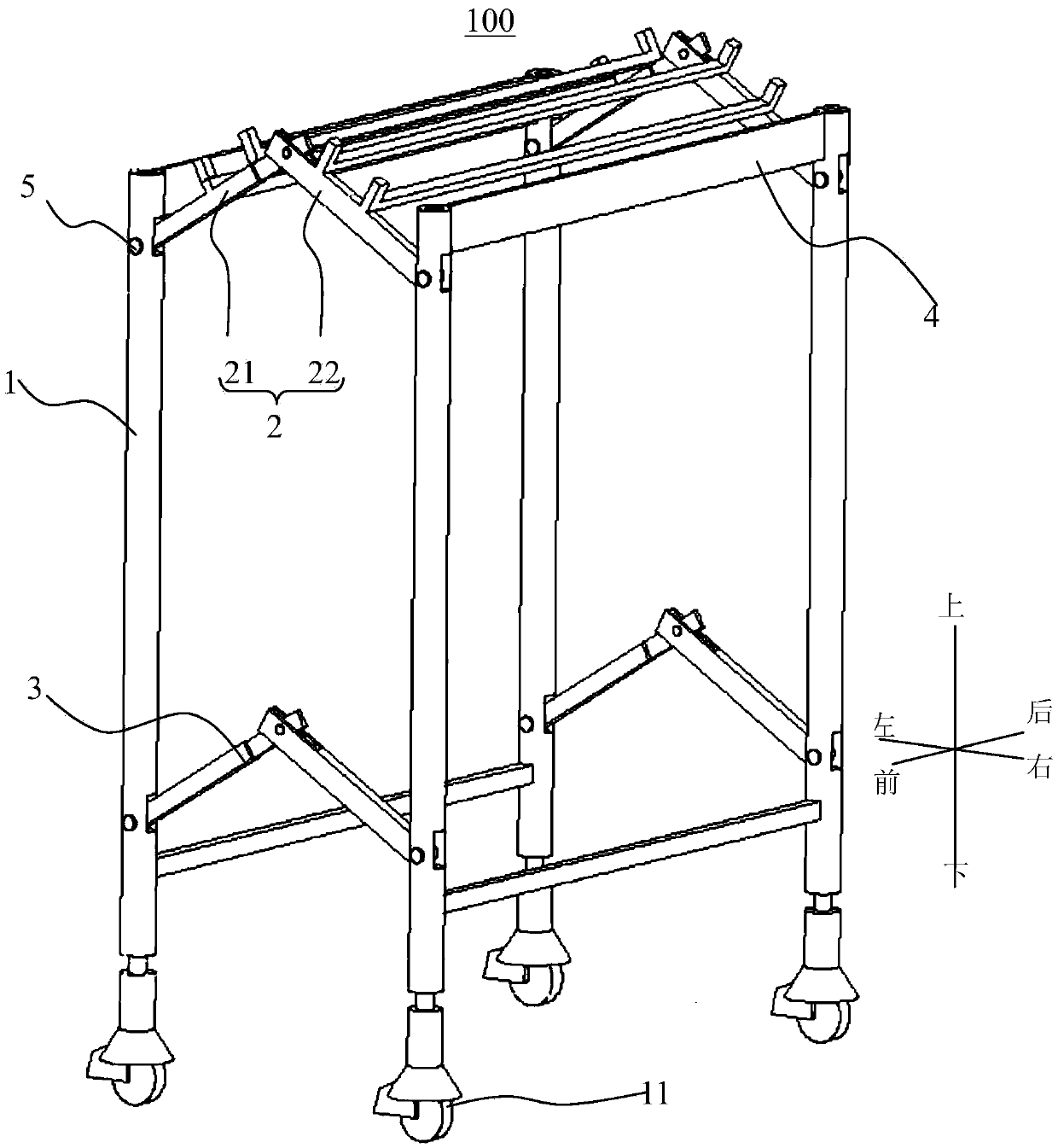
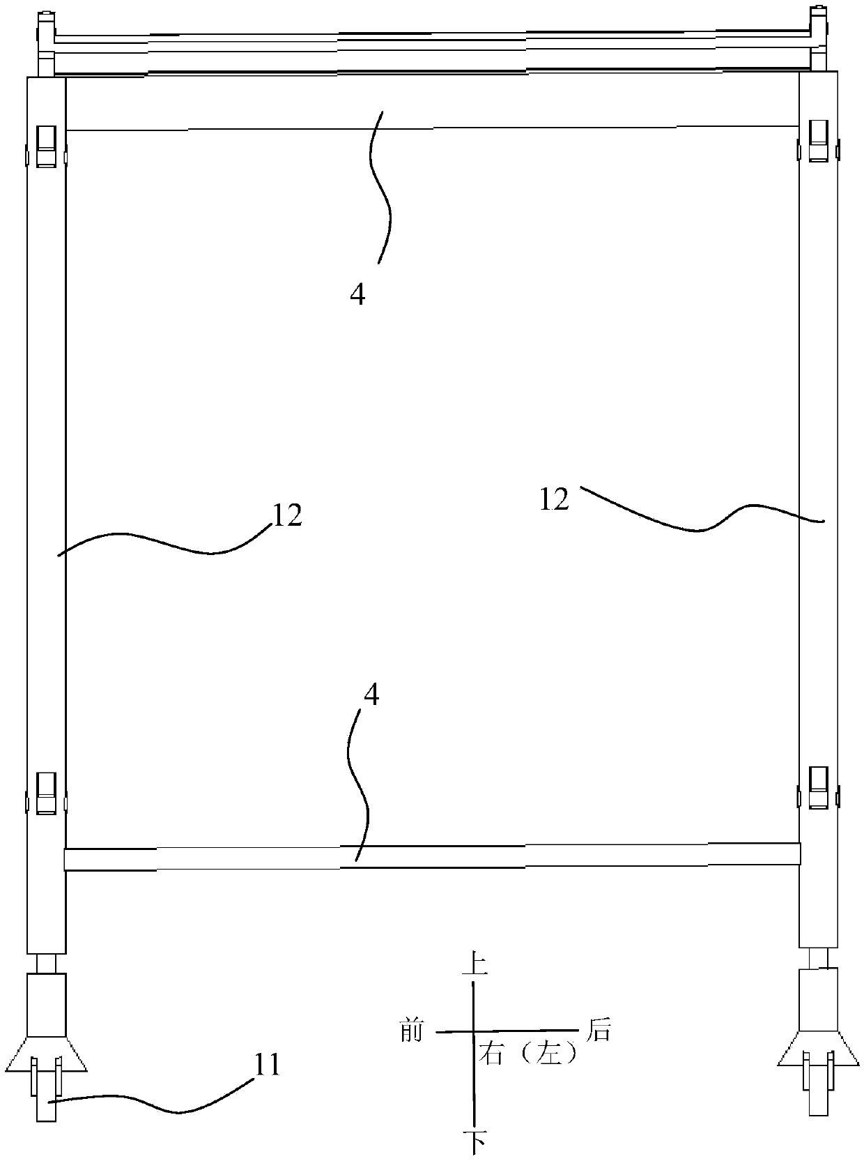
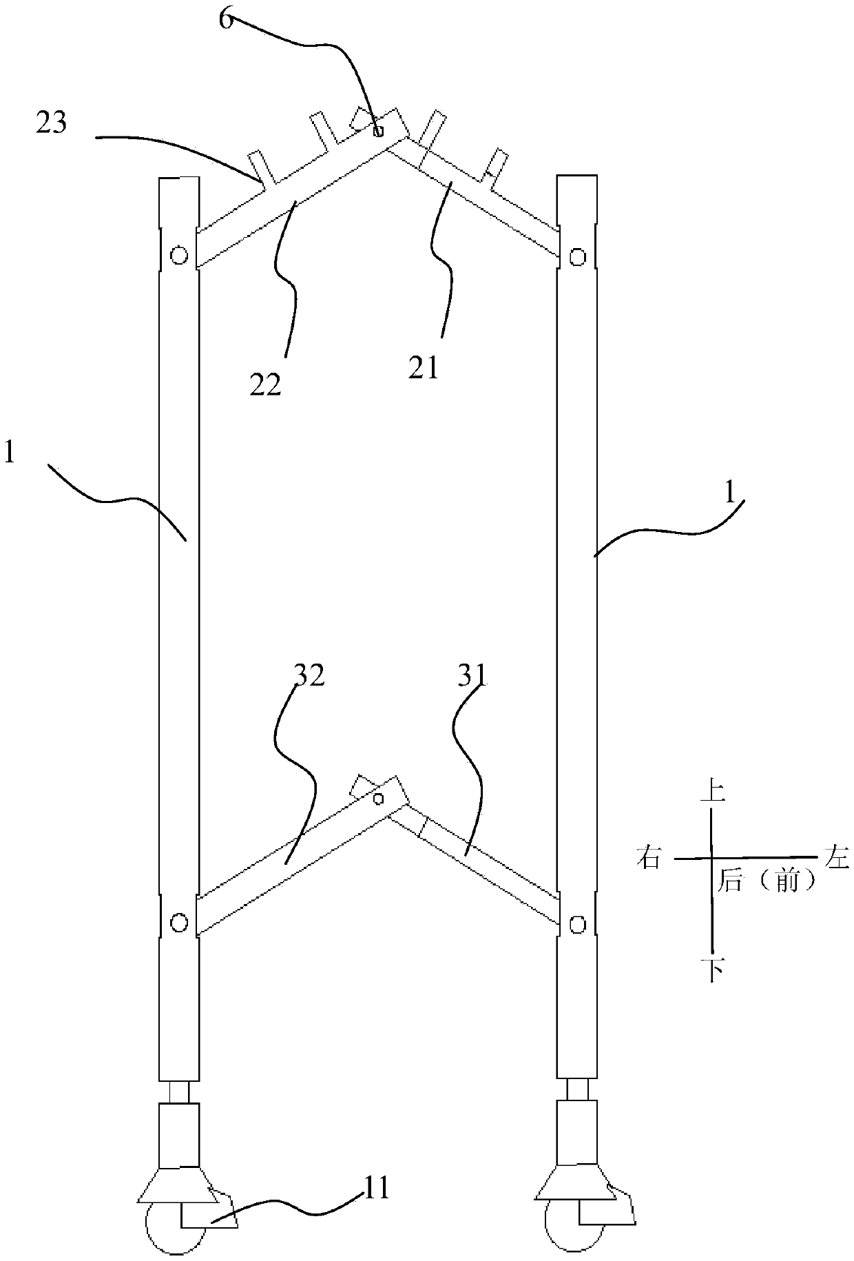
[0059] Such as Figure 1-Figure 3 As shown, the supporting frame 100 in this embodiment may include two supporting frames 1 , a placing part 2 and a stabilizing part 3 arranged oppositely. Wherein, the placing part 2 can be used for placing goods and the like.

[0060] Specifically, two brackets 1 are arranged at intervals. Each support 1 comprises two vertical rods 12, which are connected by connecting rod 4 between the two vertical rods 12, and the bottom of each vertical rod 12 is provided with a universal wheel 11 with self-locking function, each universal Wheels are movably mounted on the vertical rod 12 up and down. The connecting rod 4 is a horizontal rod.

[0061] The placing part 2 is respectively connected with the vertical rods 12 of the two brackets 1 . The placement part 2 has a storage position and an unfolded position, in terms of, as figure 1 with image 3 As shown, the placing part 2 includes a first connecting part 21 and a second connecting part 22 rot...

Embodiment 2

[0066] The supporting frame in this embodiment may include two supporting frames and a placing part arranged oppositely. Wherein, the placing part can be used for placing goods and the like.

[0067]Specifically, two brackets are arranged at intervals. Each support includes two vertical rods, which are connected by connecting rods. The bottom of each vertical rod is provided with a universal wheel with self-locking function, and each universal wheel can move up and down. on a vertical pole. The connecting rod is a horizontal rod.

[0068] The placing part is respectively connected with the two vertical rods of the two brackets. The placing part has a storage position and an unfolding position. Specifically, the placing part includes a first connecting part and a second connecting part connected with the first connecting part. A receiving space is provided under the second connecting part. The first connecting part and the second connecting part The two connecting parts are...


PUM


Abstract

The invention discloses a supporting frame which comprises two oppositely arranged supports. The two supports are spaced. The bottom of each support is provided with rotary wheels, and the rotary wheels are arranged on the supports in a vertically moving mode. The supporting frame is provided with a placement portion with a folding position and an unfolding position. The placement portion is connected with the two supports and comprises a first connection portion and a second connection portion connected with the first connection portion; when in the folding position, the first connection portion is contained below the second connection portion or the first connection portion and the second connection portion are in a folded state. According to the supporting frame, the height of the placement portion can be adjusted, and therefore production line staff put goods inside a storage box on the placement portion or take away the goods conveniently, and can also vertically move the rotary wheels to adjust the height of the corresponding supports to enable the supporting frame to be matched with the uneven ground, reliability is high, the goods can be transported, and when the supporting frame is not needed, the placement portion is made to be in the folding position so as to save the space.

Description

technical field [0001] The invention relates to the technical field of support frames, in particular to a support frame. Background technique [0002] The storage boxes used to store products on the production line are usually placed on the ground or on the round stools next to the employees’ operating stations. Static electricity and the rubber skin that relieves standing fatigue, the round stool is not stable, and the storage box placed on the round stool is easy to fall over. [0003] In addition, the storage boxes in the workshop are generally carried manually, which is laborious and easy to fall to the ground, which is unreliable. Contents of the invention [0004] The present invention aims to solve one of the technical problems in the related art at least to a certain extent. For this reason, the present invention proposes a support frame, which is convenient for workers to operate, [0005] The support frame according to the embodiment of the present invention i...

Claims


Application Information

Patent Timeline
IPC IPC(8): B25H5/00
CPCB25H5/00
Inventor 苏香平
Owner GUANGDONG OPPO MOBILE TELECOMM CORP LTD
Learn More