Multi-rotor structure applied in unmanned aerial vehicle

A technology of unmanned aerial vehicles and multi-rotors, applied in the field of multi-rotor structures, can solve the problems of cumbersome installation and disassembly work and affect the working efficiency of staff, and achieve the effect of portable operation efficiency

Inactive Publication Date: 2016-03-02
EWATT TECH CO LTD
View PDF7 Cites 43 Cited by
  • Summary
  • Abstract
  • Description
  • Claims
  • Application Information

AI Technical Summary

Problems solved by technology

[0005] The invention provides a multi-rotor structure applied to unmanned aerial vehicles, which solves or partially solves the cumbersome work of installation and disassembly when installing or disassembling several rotors of a multi-rotor unmanned aerial vehicle in the prior art, which affects the work of the staff. technical flaws in efficiency

Method used


Image

  • Multi-rotor structure applied in unmanned aerial vehicle
  • Multi-rotor structure applied in unmanned aerial vehicle
  • Multi-rotor structure applied in unmanned aerial vehicle

Examples


Embodiment 1

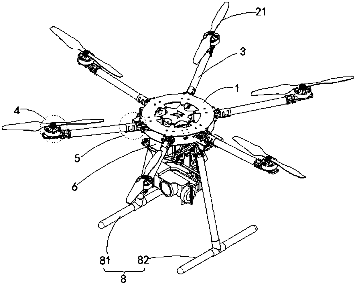
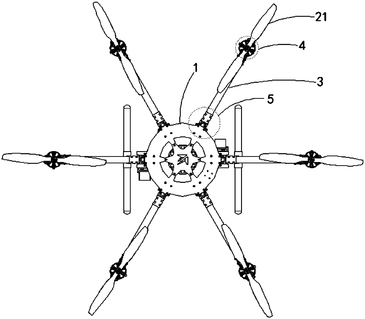
[0029] see Figure 1-2 , when the multi-rotor structure provided by Embodiment 1 of the present invention is applied to an unmanned aerial vehicle including only the first rotor 21, wherein the unmanned aerial vehicle at least includes: a fuselage 1, at least four first rotors 2, and the first A rotor shaft 3 having the same number as the first rotor 21 , a folding assembly 5 having the same number as the first rotor 21 , a sliding assembly 6 and a bracket 8 for arranging batteries. Then the multi-rotor structure includes: the same number of first rotating connecting parts 4 as the number of the first rotors 21 .

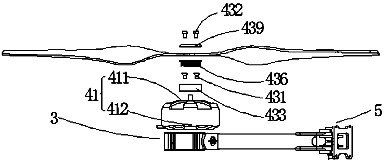
[0030] Wherein, one first rotor 21 is detachably connected to one rotor shaft 3 through one first rotary connecting member 4 . please if Figure 3-4 As shown, the first rotary connector 4 at least includes: a first motor 41 and a first dismounting thread group 43 . The first motor 41 is used to drive the first rotor 21 to rotate, so as to drive the fuselage 1 to ...

Embodiment 2

[0057] Take the twelve-rotor unmanned aerial vehicle as embodiment two of the present invention, because Figure 1-2 The multi-rotor structure shown is applied to a hexacopter UAV, which adopts a single propeller and a single shaft, that is, each rotor shaft 3 is equipped with a first motor 41 and a first rotor 21 . when Figure 1-2 When the shown multi-rotor structure is applied to twelve rotors, the multi-rotor structure includes: the same number of first rotary connectors 4 as the first rotor 21 and the same number of second rotary connectors 22 . When its each rotor shaft 3 is equipped with two motors and two rotors, that is to say, all adopt dual-blade coaxiality (two rotors share a rotor shaft 3), that is, form a multi-rotor structure that twelve rotors are applied to unmanned aerial vehicles. Can be like Figure 11 shown.

[0058] At this time, one end of the rotor shaft 3 used to connect to the fuselage 1 is used as the connection end 32 , and is rotatably connected...


PUM


Abstract

The present invention discloses a multi-rotor structure applied in unmanned aerial vehicle, and belongs to the technical field of unmanned aerial vehicle. The unmanned aerial vehicle includes a fuselage, first rotors, second rotors, and rotor shafts, and further includes first rotating connecting pieces and second rotating connecting pieces. Each rotating connecting piece comprises a first motor and first dismounting screw thread group; and the first rotor is detachably connected to the first motor through the first dismounting screw group, so that the installation or dismounting between the first rotor and the first motor can be realized by rotating the first rotor. Each second rotating connecting piece comprises a second motor and second dismounting screw thread group; and the second rotor is detachably connected to the second motor through the second dismounting screw group, so that the installation or dismounting between the second rotor and the second motor can be realized by rotating the second rotor. The multi-rotor structure has the characteristics of fastness, convenience and high working efficiency.

Description

technical field [0001] The invention belongs to the technical field of unmanned aerial vehicles, and in particular relates to a multi-rotor structure applied to unmanned aerial vehicles. Background technique [0002] Unmanned aircraft, referred to as "UAV", is an unmanned aircraft controlled by radio remote control equipment and its own program control device. There is no cockpit on board, but it is equipped with autopilot, program control device, information collection device and other equipment. The personnel on the ground, on the ship, or at the remote control station of the parent aircraft track, locate, remotely control, telemeter and digitally transmit it through radar and other equipment. Under the radio control, it can take off like an ordinary aircraft or be launched into the air with a booster rocket, and it can also be taken into the air by the parent aircraft for flight. [0003] In the UAV in the prior art, a drive motor is usually fixed at the end of the roto...

Claims


Application Information

Patent Timeline
Patent Type & Authority Applications(China)
IPC IPC(8): B64C27/08
CPCB64U10/10B64U50/30B64U30/293B64U50/19B64U10/16B64U80/20B64C27/001B64C27/32B64U10/13B64U30/20B64U80/00B64C39/024B64C27/08
Inventor 赵国成范晖陈方芳
Owner EWATT TECH CO LTD
Why Eureka
Try Eureka