Stacking machine

A technology of stacker and frame, applied in the field of stacker, can solve the problems of large clamping action range, difficult replacement, high cost, etc., and achieve the effect of small operation range, high installation efficiency and low installation cost

Inactive Publication Date: 2016-03-02
SUZHOU YING CHUANG POWER TECH +5
View PDF0 Cites 19 Cited by
  • Summary
  • Abstract
  • Description
  • Claims
  • Application Information

AI Technical Summary

Problems solved by technology

However, the stacker in the prior art has a large investment cost, complex structure, inconvenient operation, low work efficiency, and certain limitations in handling; The reliability is not high, the clamping action range is large, the operation stability is not high, and it is easy to generate vibration and damage the internal components; the unstacking disc device moves up and down on the frame through the lifting and sliding device to realize the lifting and placing of the turnover box Operation, rely on the sliding device to slide during the lifting movement, the existing sliding device adopts a special slide rail structure, its cost is high, the structure is complicated, and it is not easy to replace

Method used


Image

  • Stacking machine
  • Stacking machine
  • Stacking machine

Examples


Embodiment Construction

[0050] The specific implementation manner of the present invention will be described below in conjunction with the accompanying drawings.

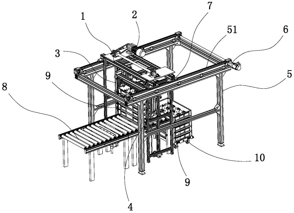
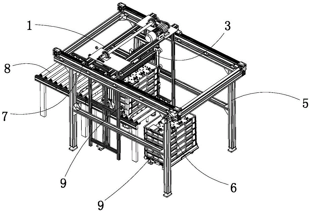
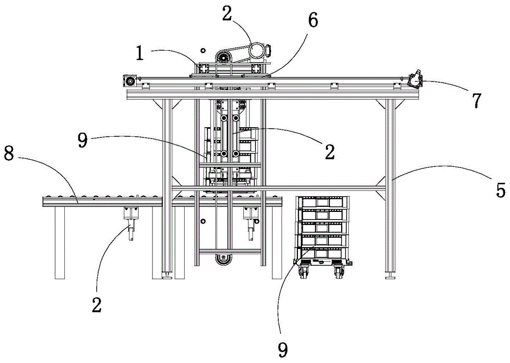
[0051] like Figure 1 to Figure 3 As shown, a kind of stacker of the present embodiment comprises a frame 5, a conveying positioning mechanism 8 installed on the frame 5 and a stacking tray mechanism, and the stacking tray mechanism is placed above the conveying positioning mechanism 8, and The stacking mechanism is mounted on the horizontal slide rail 51 at the top of the frame 5 through the horizontal slider 7 sliding device and driven by the mobile motor 6 on one side of the top of the frame 5. 7 is connected to realize the horizontal driving of the horizontal slider 7.

[0052] like Figure 4 to Figure 7 As shown, the stacking tray structure includes: the outer bracket 1 and the stacking tray device 3 installed in the outer bracket 1, the stacking tray device 3 slides on the outer bracket 1 through the slider structure 4 and passes t...


PUM


Abstract

The invention relates to a stacking machine. The stacking machine comprises a machine frame, a conveying and positioning mechanism and a folding disc mechanism, wherein the conveying and positioning mechanism and the folding disc mechanism are arranged on the machine frame. The folding disc mechanism is arranged above the conveying and positioning mechanism, arranged on horizontal sliding rails at the top of the machine frame in a sliding manner through horizontal sliding blocks and driven by a movement motor on one side of the top of the machine frame. The folding disc mechanism comprises a folding disc device, and the folding disc device can vertically slide on a sliding block support through a sliding block structure to clamp and release a circulation box. The stacking machine is simple in structure, reliable in work and low in cost.

Description

technical field [0001] The invention relates to the technical field of logistics transportation packaging, in particular to a stacker for turnover boxes of electric meters, concentrators and other devices. Background technique [0002] Nowadays, logistics technology has attracted more and more attention, and warehouses play a key role in the logistics system. The stacker plays the role of storing goods in the whole system, which is an indispensable link in the automatic three-dimensional warehouse. The stacker technology is the core of the entire automated warehouse technology. At present, single-phase ammeters, three-phase ammeters, concentrators and other devices are packaged in turnover boxes. The turnover boxes need to be stacked on trolleys or unstacked from trolleys. Stackers are indispensable equipment. However, the stacker in the prior art has a large investment cost, complex structure, inconvenient operation, low work efficiency, and certain limitations in handling...

Claims


Application Information

Patent Timeline
Patent Type & Authority Applications(China)
IPC IPC(8): B65G61/00B65G57/32B65G59/12
Inventor 何锡斌孟静郑安刚赵静巫钟兴章鹿华续展和丁恒春柳青解玉满谈晓妍杨乃贵邵淮岭王雍侯慧娟代迎凯秦松峰吴宏波
Owner SUZHOU YING CHUANG POWER TECH
Why Eureka
Try Eureka