Gallery bridge with fire-fighting lanes

A technology for fire protection and lanes, applied in bridges, buildings, building structures, etc., can solve problems such as buried hidden dangers, unreserved special fire-fighting passages in corridor bridges, and crowded passages, so as to improve patency, improve and evacuate the flow of people Effect

Inactive Publication Date: 2016-03-02
田海荣
View PDF7 Cites 2 Cited by
  • Summary
  • Abstract
  • Description
  • Claims
  • Application Information

AI Technical Summary

Problems solved by technology

As the corridor bridge is a crowded place, the passages on the corridor bridge are relatively crowded, so the existi

Method used


Image

  • Gallery bridge with fire-fighting lanes

Examples


Embodiment Construction

[0013] The present invention will be described in detail below in conjunction with the accompanying drawings and specific embodiments.

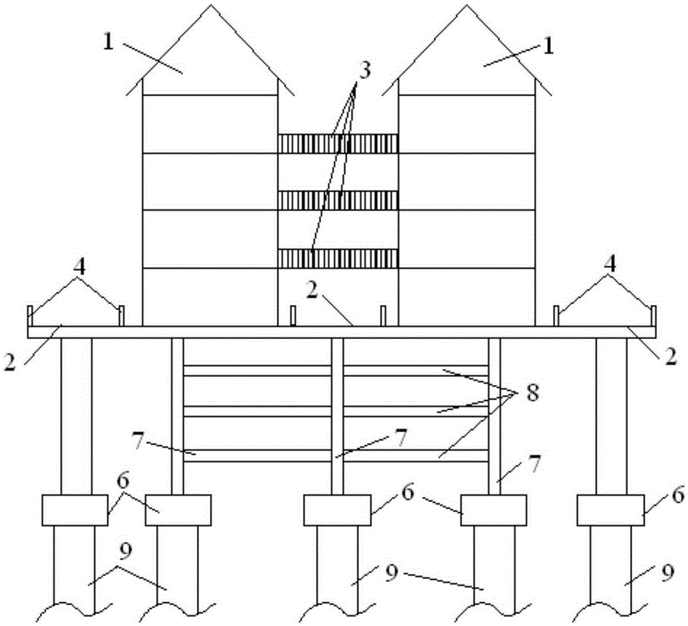
[0014] The invention provides a corridor bridge with a fire lane, see figure 1 A gallery 1 is arranged above the covered bridge body, and a fire lane 2 is provided on one or both sides of the covered bridge, and the fire lane 2 extends along the direction of the covered bridge.

[0015] One or more corridors 1 can be set on the corridor bridge, and when there are many corridors 1, a fire lane 2 dedicated to fire rescue can be set between two corridors 1.

[0016] Since the corridor bridge only involves static loads, the corridor bridge is designed and constructed according to the integrated structure, while the fire lane 2 involves static loads and dynamic loads, so the fire lane 2 is constructed according to the standards for highway bridge structure design.

[0017] Corridor 1 can also be set to one or more layers, when corridor 1 is multi...


PUM


Abstract

The invention discloses a gallery bridge with fire-fighting lanes. The gallery bridge comprises a gallery bridge body constructed according to integrated structural design, wherein one or more bungalows are arranged above the gallery bridge body and are one-layer or multi-layer, the fire-fighting lanes constructed according to a highway bridge structure design are arranged on the single side or two sides of the gallery bridge, extend along the gallery bridge and are arranged on two sides of the gallery bridge, and the fire-fighting smoothness and people flow evacuation are greatly improved.

Description

technical field [0001] The invention belongs to the technical field of bridge construction and relates to a covered bridge with a fire lane. Background technique [0002] Covered bridges, also known as Hongqiao, centipede bridges, etc., are bridges with a roof, which can protect the bridge, and at the same time provide shade and shelter, and provide people with rest, communication, and gathering functions. Because the corridor bridge is a crowded place, the passages on the corridor bridge are relatively crowded, so the existing corridor bridge does not reserve special passages for fire protection, which bury hidden dangers for fire safety. Contents of the invention [0003] Aiming at the deficiencies of the above-mentioned prior art, the present invention provides a covered bridge with a fire lane. [0004] The technical scheme adopted in the present invention is, a corridor bridge with a fire lane, including a corridor bridge designed and constructed according to an inte...

Claims


Application Information

Patent Timeline
IPC IPC(8): E01D1/00E04H14/00
CPCE01D1/00E04H14/00
Inventor 田海荣
Owner 田海荣
Why Eureka
Try Eureka