
Mixing drum synchronization box

A technology for synchronizing boxes and boxes, which is applied to portable lifting devices, transmission parts, gear transmissions, etc., can solve the problems of increasing the labor intensity of maintenance workers, increasing the time and frequency of downtime for maintenance, and the high frequency of driving gears. , to achieve the effect of reducing material maintenance costs, oil and maintenance labor intensity, reducing the time and frequency of downtime for maintenance, and improving production efficiency

Inactive Publication Date: 2016-03-02
JINAN AOHAI CARBON PROD
View PDF5 Cites 0 Cited by
  • Summary
  • Abstract
  • Description
  • Claims
  • Application Information

AI Technical Summary

Problems solved by technology

[0002] The currently used mixing drum synchronous box often has the phenomenon of gear teeth beating, resulting in broken gear teeth, and it is necessary to stop production for maintenance and replacement of gears, which increases material costs and labor intensity of maintenance workers, and affects production; at the same time, the driving gear set in the mixing drum synchronous box is due to The frequency of occlusion is high, the wear is serious, and it needs to be replaced frequently, which increases the time and frequency of downtime and maintenance

Method used


Image

  • Mixing drum synchronization box
  • Mixing drum synchronization box

Examples


Embodiment 1

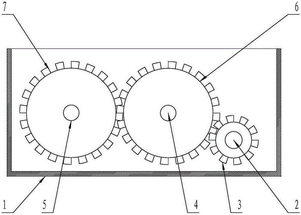
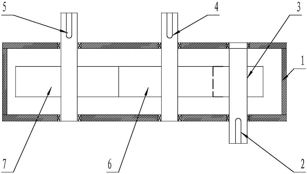
[0013] Such as figure 1 , figure 2 As shown, a mixing drum synchronous box includes a mixing drum synchronous box 1 and a drive gear shaft 2. The mixing drum synchronous box 1 has two opposite side plates and a horizontal plate enclosing the two side plates. The drive gear shaft 2 is installed on the opposite two side plates of the mixing drum synchronous box body 1 using bearings. A drive gear 3 is installed on the part where the shaft 2 extends into the synchronous box body 1 of the mixing drum, and it is characterized in that: it also includes A driven gear shaft 4, B driven gear shaft 5, said A driven gear shaft 4, The B driven gear shaft 5 is respectively installed on two opposite side plates of the mixing drum synchronous box body 1 using bearings in parallel. The A driven gear shaft 4 and the B driven gear shaft 5 also have The parts of the two side plates opposite to the body 1, the A driven gear shaft 4 and the B driven gear shaft 5 are respectively installed on th...

Embodiment 2

[0015] Such as figure 1 , figure 2 As shown, a mixing drum synchronous box includes a mixing drum synchronous box 1 and a drive gear shaft 2. The mixing drum synchronous box 1 has two opposite side plates and a horizontal plate enclosing the two side plates. The drive gear shaft 2 is installed on the opposite two side plates of the mixing drum synchronous box body 1 using bearings. A drive gear 3 is installed on the part where the shaft 2 extends into the synchronous box body 1 of the mixing drum, and it is characterized in that: it also includes A driven gear shaft 4, B driven gear shaft 5, said A driven gear shaft 4, The B driven gear shaft 5 is respectively installed on two opposite side plates of the mixing drum synchronous box body 1 using bearings in parallel. The A driven gear shaft 4 and the B driven gear shaft 5 also have The parts of the two side plates opposite to the body 1, the A driven gear shaft 4 and the B driven gear shaft 5 are respectively installed on th...


PUM


Abstract

The invention discloses a mixing drum synchronization box for stirring an anode printing paste. The mixing drum synchronization box comprises a mixing drum synchronization box body, a drive gear, a driven gear A and a driven gear B, wherein the drive gear is installed on a part, extending into the mixing drum synchronization box body, of a drive gear shaft; the driven gear A and the driven gear B are installed on parts, extending into the mixing drum synchronization box body, of a driven gear shaft A and a driven gear shaft B respectively; the drive gear is meshed with the driven gear A; the driven gear A is meshed with the driven gear B; the tooth widths of the driven gear A, the driven gear B and the drive gear are 140-160mm respectively; and the drive gear is made of forged steel. With the adoption of the mixing drum synchronization box, the phenomenon about tooth beating of the driven gear A, the driven gear B and the drive gear of the mixing drum synchronization box is prevented, the service life of the drive gear is prolonged as the material of the drive gear is improved, the time and the frequency for halt overhauling of the mixing drum synchronization box are reduced, the material maintenance cost is lowered, the maintenance labor intensity is weakened, and the production efficiency is improved.

Description

technical field [0001] The invention belongs to a component product for stirring the paste of an anode vibration forming machine, in particular to a mixing drum synchronous box. Background technique [0002] The currently used mixing drum synchronous box often has the phenomenon of gear teeth beating, resulting in broken gear teeth, and it is necessary to stop production for maintenance and replacement of gears, which increases material costs and labor intensity of maintenance workers, and affects production; at the same time, the driving gear set in the mixing drum synchronous box is due to The frequency of occlusion is high, the wear is serious, and it needs to be replaced frequently, which increases the time and frequency of downtime for maintenance. How to make a mixing drum synchronous box gear that can prevent the gear from beating, improve the wear resistance of the driving gear set in the mixing drum synchronous box, prolong its service life, reduce material maintena...

Claims


Application Information

Patent Timeline
Patent Type & Authority Applications(China)
IPC IPC(8): F16H1/20F16H57/023F16H55/06F16H55/17
CPCF16H1/20F16H55/06F16H55/17F16H57/023F16H2057/02039
Inventor 赵庆才尹燕岱刘大伟尹诚诚李绪亮胡业涛赵庆波翟美
Owner JINAN AOHAI CARBON PROD
Learn More