
Error calibration and compensation method for accelerometer unit of inertially stabilized platform system

An inertial stable platform and accelerometer technology, applied in the field of inertial stable platform system calibration, can solve the problem of large residual error in multi-position fitting

Inactive Publication Date: 2016-03-02
BEIJING INST OF AEROSPACE CONTROL DEVICES
View PDF2 Cites 19 Cited by
  • Summary
  • Abstract
  • Description
  • Claims
  • Application Information

AI Technical Summary

Problems solved by technology

[0006] Since the current error model only considers the two errors of the accelerometer zero bias and the scale factor, the residual error of the multi-position fitting after the error coefficient compensation under the power-on condition is relatively large

Method used


Image

  • Error calibration and compensation method for accelerometer unit of inertially stabilized platform system
  • Error calibration and compensation method for accelerometer unit of inertially stabilized platform system
  • Error calibration and compensation method for accelerometer unit of inertially stabilized platform system

Examples


Embodiment 1

[0106] In the current inertial stabilization system, the error model of accelerometer combination is:

[0107] A x A y A z = K 0 x K 0 y K 0 z + K a ...


PUM


Abstract

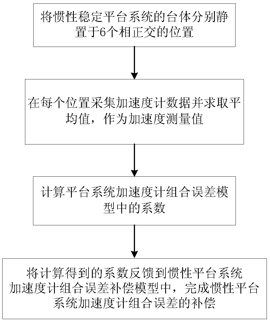
The invention discloses an error calibration and compensation method for an accelerometer unit of an inertially stabilized platform system. When the inertially stabilized platform system is in a stationary base state, the platform body achieves six orthogonal positions relative to the inertial space; through data processing on the accelerometer unit, 15 error coefficients can be calibrated and isolated; and after error compensation, the fitting residual error can be significantly reduced. Compared to other calibration method of error coefficient, the method completes error coefficient calibration and compensation of three axis accelerometers in the inertially stabilized platform system, not only improves the precision of error coefficient calibration, but also realizes simple calibration process and short time.

Description

technical field [0001] The invention relates to an inertial stable platform system calibration technology, in particular to an inertial stable platform system accelerometer combination error calibration and compensation method, which can be used to realize the self-calibration of a high-precision inertial measurement system. Background technique [0002] The accelerometer is one of the basic measuring elements of the inertial stable platform system. The accelerometer composed of it is installed on the platform body to measure the motion acceleration of the carrier, and its velocity and position can be obtained by integrating the acceleration. . Therefore, the performance and accuracy of accelerometers directly affect the accuracy of navigation and guidance systems. [0003] When installed inside the vehicle, the output value of the accelerometer not only includes the acceleration of the accelerometer shell moving with the vehicle, the Gothic acceleration caused by the movem...

Claims


Application Information

Patent Timeline
IPC IPC(8): G01C25/00G01C21/16G01P21/00G01P15/18G01P15/02
CPCG01C21/16G01C25/005G01P15/02G01P15/18G01P21/00
Inventor 魏宗康赵长山周元
Owner BEIJING INST OF AEROSPACE CONTROL DEVICES
Learn More