Low voltage district electric energy meter phase line identification method

A technology of low-voltage station area and identification method, applied in electrical signal transmission systems, signal transmission systems, instruments, etc., can solve the problems of heavy phase line workload, uneconomical operation of transformers, and inability to achieve refined management of power supply phases. To achieve the real effect of recognition results

Inactive Publication Date: 2016-03-02
STATE GRID CORP OF CHINA +2
View PDF6 Cites 11 Cited by
  • Summary
  • Abstract
  • Description
  • Claims
  • Application Information

AI Technical Summary

Problems solved by technology

At present, the power supply company has accumulated large-scale low-voltage power supply customers with a large number of meters. The power supply company dispatches operators to the location of the meters, all relying on manual work to check and mark the phase lines where the meters are located. Due to business impacts such as meter replacement, manual marking cannot be synchronized in time, and there is a phenomenon that the meter is replaced immediately after marking, which objectively results in a situation where the phase lines of the meter are almost impossible to sort out
Phase-separated data cannot be consistent with the actual situation, power supply phase-separated refined management cannot be realized, and transformer operation is uneconomical

Method used


Image

  • Low voltage district electric energy meter phase line identification method
  • Low voltage district electric energy meter phase line identification method
  • Low voltage district electric energy meter phase line identification method

Examples


Embodiment Construction

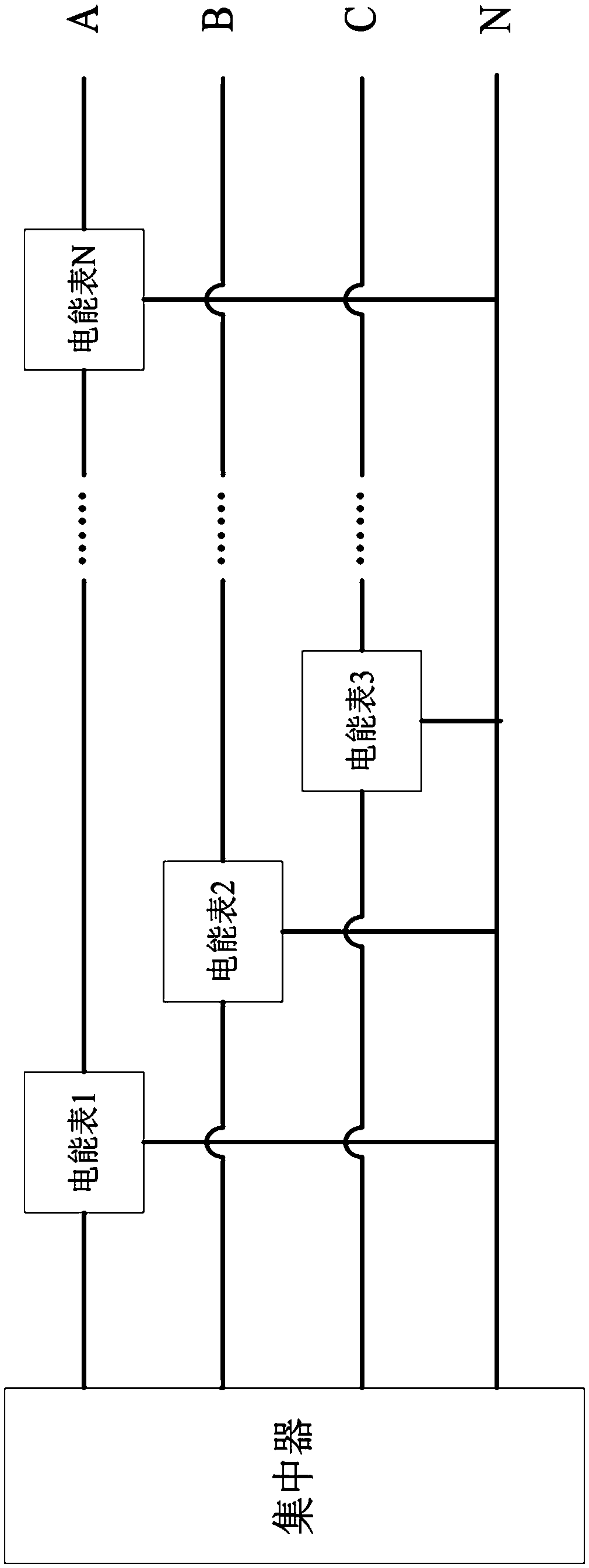
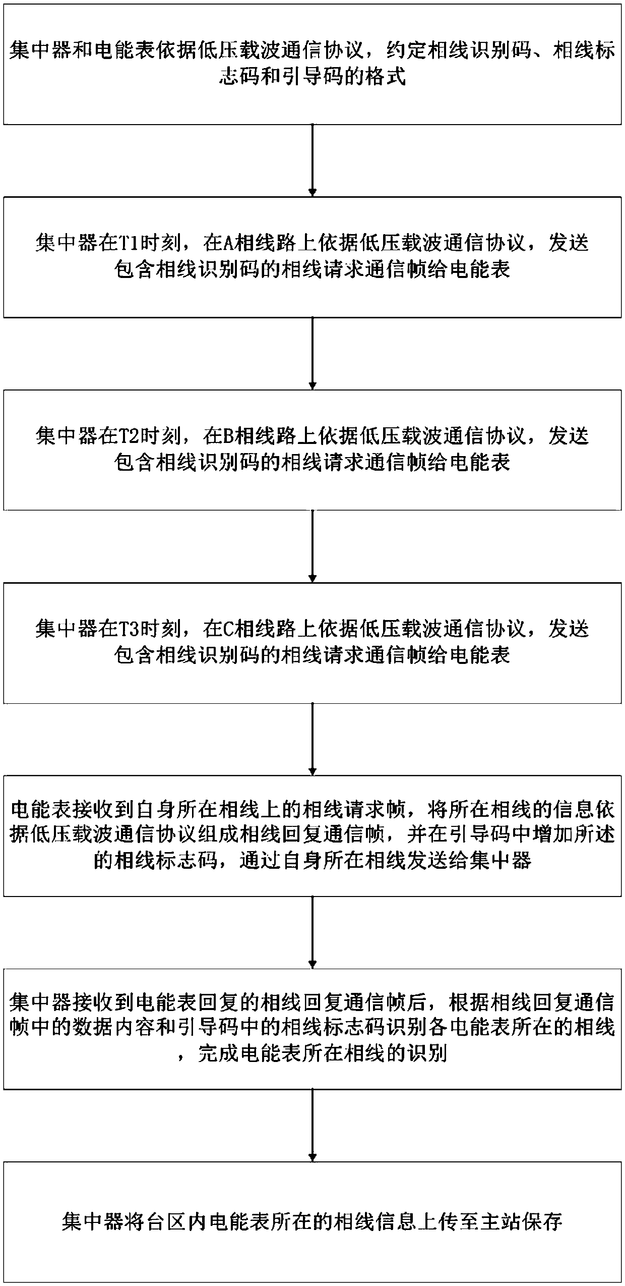
[0022] Such as figure 2 Shown is the method flowchart of the present invention: the identification method of the phase line where the low-voltage station area electric meter of the present invention is located specifically comprises the following steps:

[0023] S1. The concentrator and the energy meter agree on the format of the phase wire identification code and the pilot code according to the low-voltage carrier communication protocol;

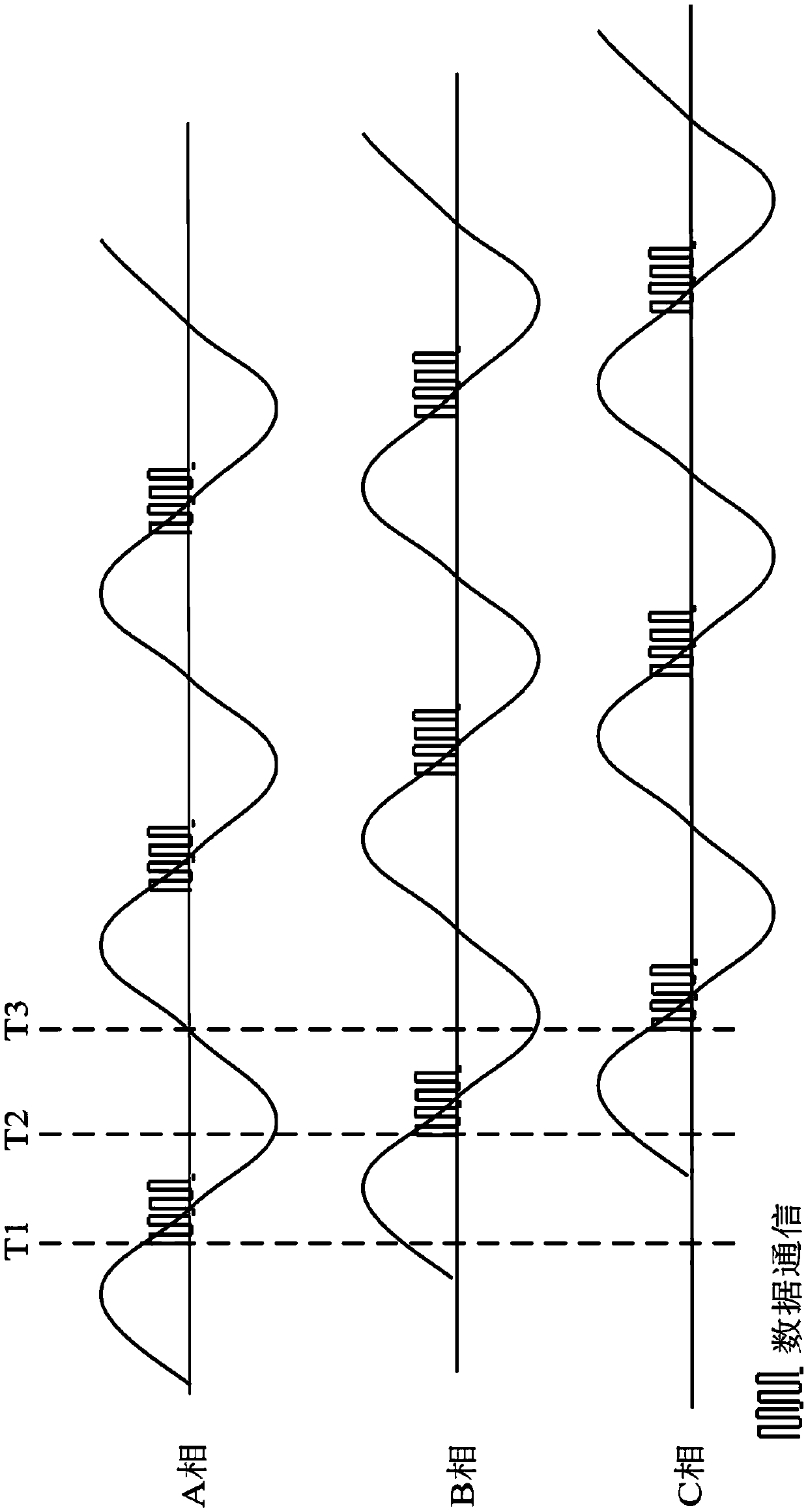
[0024] S2. At three different times, the concentrator sends phase line request communication frames to the electric energy meter on the three-phase line according to the low-voltage carrier communication protocol, requesting the electric energy meter to return the information of the phase line where each electric energy meter is located, and at the same time only Send a phase line request communication frame on a single phase line;

[0025] At time T1, the concentrator sends a phase line request communication frame to the energy meter on ...


PUM


Abstract

The present invention discloses a low voltage district electric energy meter phase line identification method which is as follows: a concentrator and electric energy meters appoint phase line mark code and guidance code formats; the concentrator sends phase line request communication frames to the electric energy meters in different time and in different phases to request the electric energy meters to return phase line information of each electric energy meter; the electric energy meters constitute phase line reply communication frames, add phase line mark codes into guidance codes of the phase line reply communication frames, and send to the concentrator by the phase lines of the electric energy meters; and the concentrator completes the identification of the phase lines of the electric energy meters according to the identification of data content in the phase line reply communication frames and the phase line mark codes in the guidance codes. According to the method, by the low voltage carrier wave communication mode of sending and replying in different time and in different phases, the identification works of the phase lines of the electric energy meters can be automatically completed, in the manner of adding of the phase line mark codes after the guidance codes of the communication frames, dual identification of the phase lines of the electric energy meters can be completed, and real, reliable and accurate results of the identification of the phase lines of the electric energy meters can be ensured.

Description

technical field [0001] The invention specifically relates to a method for identifying the phase line where the electric meter is located in a low-voltage station area. Background technique [0002] With the development of the country's economy and technology, power system automation has been greatly developed. As a device for measuring point energy, the electric meter plays an irreplaceable role in the power system. At this stage, the layout of the low-voltage station area of ​​the power grid is as follows: figure 1 As shown: the low-voltage side of the transformer is the starting end of a low-voltage station area, and the station area master meter and the station area communication concentrator are installed on the low-voltage side of the transformer. The concentrator is connected to each electric meter in the station area through the low-voltage power supply network; centralized The device uses low-voltage carrier to communicate with each meter. The low-voltage carrier ...

Claims


Application Information

Patent Timeline
Patent Type & Authority Applications(China)
IPC IPC(8): G08C19/00
CPCG08C19/00
Inventor 朱佐平贺铁光贺常德刘小江许弢张尉夏晓霖郭冰
Owner STATE GRID CORP OF CHINA
Why Eureka
Try Eureka