Method for reducing grounding resistance in manner of digging grounding deep well in transformer station

A grounding resistance, substation technology, applied in circuits, connections, electrical components, etc., can solve the problems of high experience requirements, impossible to talk about, waste of financial and material resources, etc., to achieve high soil resistivity, simple design, and reduce the effect of grounding resistance.

Active Publication Date: 2016-03-02
ANHUI HUADIAN ENG CONSULTATING & DESIGN
View PDF6 Cites 5 Cited by
  • Summary
  • Abstract
  • Description
  • Claims
  • Application Information

AI Technical Summary

Problems solved by technology

[0002] A good grounding system is the basic guarantee for the safe, reliable, and stable operation of substations. However, the site selection of domestic substations is often located in areas with high land resistance such as fertile land, residential areas, and economic development zones. The area with high power rate and poor address conditions brings great challenges to the design of the substation grounding system, so a reliable and excellent grounding system is required
[0003] At present, the domestic grounding system design generally adopts the following steps: Calculate the grounding resistance value, the contact potential difference in the station and the minimum value of the step potential difference according to the measured value of soil resistivity, the maximum valu

Method used


Image

  • Method for reducing grounding resistance in manner of digging grounding deep well in transformer station
  • Method for reducing grounding resistance in manner of digging grounding deep well in transformer station
  • Method for reducing grounding resistance in manner of digging grounding deep well in transformer station

Examples


Embodiment 1

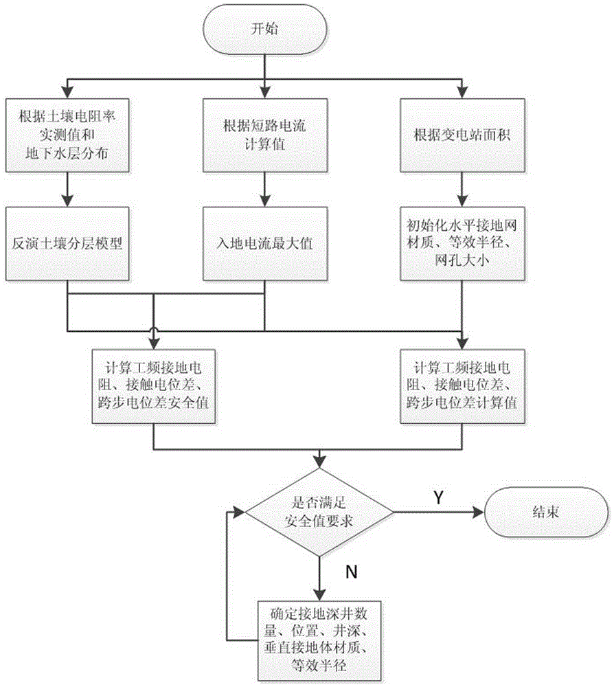
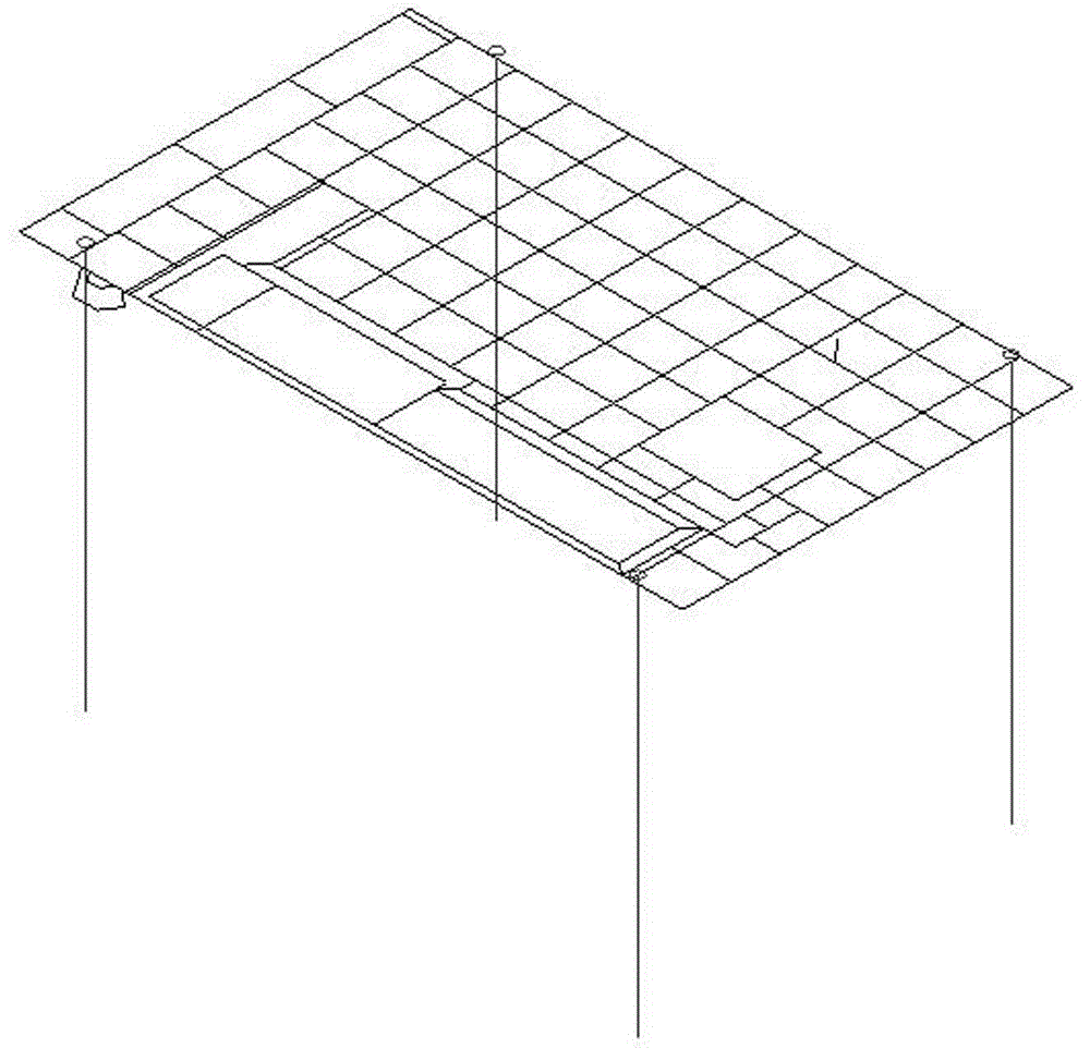
[0016] Embodiment 1, with reference to Figure 1-2 , Embodiment 1 takes a 110kV substation in Anqing, Anhui as an example:

[0017] (1) Initial conditions of substation grounding system

[0018] 1) The measured value of soil resistivity and geological conditions,

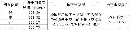
[0019] The substation is located in the Anqing area. The size of the station area is 48m×81.5m. The measured value of the soil resistivity at the location is relatively high, as shown in Table 1. According to the survey professional "Geotechnical Engineering Survey Report", the foundation rock and soil of this station are 0.5m~4.2 m is silty clay, and the buried depth of groundwater at first sight is 3.5~4.5m.

[0020] Table 1

[0021]

[0022] 2) The initial parameters of the horizontal grounding grid are shown in Table 2, and the maximum value of the calculated grounding current is 3.43kA.

[0023] Table 2

[0024] Material of horizontal ground grid Section (mm*mm) Mesh size (mm*mm) Buried ...


PUM


Abstract

The invention discloses a method for reducing grounding resistance in manner of digging a grounding deep well in a transformer station, comprising steps of calculating a station address soil layered model, calculating target parameters like a power frequency grounding resistance safety value of a horizontal grounding grid and safety values of a contact potential difference and a step potential difference, obtaining a power frequency grounding resistance calculation value of a horizontal grounding grid and calculation values of the contact potential difference and the step potential difference, determining the amount, the positions, the well depth, the perpendicular grounding electrode materials and equivalent radiuses of the grounding deep wells, regulating the parameters of the grounding deep well, providing a horizontal grounding grid material table, a perpendicular grounding body material table, rise of earth potential, the power frequency grounding resistance, the calculation values and the safety values of the contact potential difference and the step potential difference of the grounding grid of the station. The invention can dramatically reduce the grounding resistance of the transformer station, enables the contact potential difference and the step potential difference to be reduced to below the safety value, and enables the design of the high soil resistivity and transformer station grounding system having the ground water layer to be simple, accurate and effective.

Description

Technical field: [0001] The invention relates to the technical field of substation grounding systems, in particular to a method for reducing grounding resistance by drilling deep ground wells. Background technique: [0002] A good grounding system is the basic guarantee for the safe, reliable, and stable operation of substations. However, the site selection of domestic substations is often located in areas with high land resistance such as fertile land, residential areas, and economic development zones. Areas with high power and poor address conditions bring great challenges to the design of the substation grounding system, so a reliable and high-performance grounding system is required. [0003] At present, the domestic grounding system design generally adopts the following steps: Calculate the grounding resistance value, the contact potential difference in the station and the minimum value of the step potential difference according to the measured value of soil resistivity...

Claims


Application Information

Patent Timeline
IPC IPC(8): H01R4/66H01R43/00
CPCH01R4/66H01R43/00
Inventor 盛晓云宋云燕
Owner ANHUI HUADIAN ENG CONSULTATING & DESIGN
Why Eureka
Try Eureka