A long-life wireless power transmission device between rotating interfaces of moving parts

A technology for wireless power transmission and moving parts, applied in circuit devices, electrical components, etc., can solve the problems of not fully satisfying long-life power transmission, inability to discharge during grinding, poor thermal conductivity, etc., and achieve stable and reliable power transmission process. The effect of impedance matching and extending transmission distance

Inactive Publication Date: 2018-04-24
NAT UNIV OF DEFENSE TECH
View PDF4 Cites 0 Cited by
  • Summary
  • Abstract
  • Description
  • Claims
  • Application Information

AI Technical Summary

Problems solved by technology

However, there are many deficiencies in the conductive slip ring: First, the conductive ring is worn. If the lubricant content is high, the wear amount is small, but the conductivity becomes poor; on the contrary, the lubricant content is small, the conductivity is good, but the wear amount increases
The second is that the contact part between the slip ring and the brush generates a lot of heat. Since the channels of the conductive ring must be insulated, and the insulating material usually has poor thermal conductivity, it is difficult to realize the heat dissipation of the conductive ring through conduction.
[0003] To this end, people have also tried some new methods to transmit electric energy to rotating parts, such as the use of rolling ring technology to change sliding friction into rolling friction, which reduces the amount of wear, but there are still problems such as uneven stress on rolling elements and inability to discharge during grinding. ;Using mercury collector ring technology, using liquid metal instead of sliding friction, no friction, but difficult to seal; using optical collector ring technology, using non-contact optical fiber as the transmission medium, but the power that can be transmitted is small
Therefore, none of these technologies can fully meet the needs of long-life power transmission between rotating interfaces of moving parts

Method used


Image

  • A long-life wireless power transmission device between rotating interfaces of moving parts
  • A long-life wireless power transmission device between rotating interfaces of moving parts

Examples


Embodiment Construction

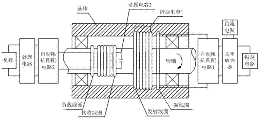
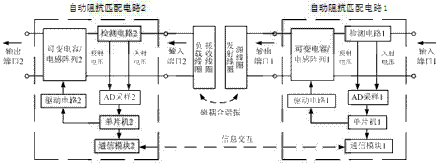
[0014] The long-life wireless power transmission device between the rotating interfaces of movable parts provided by the present invention, such as figure 1 As shown, it includes a base body, a rotating shaft set in the base body, a fixed part and a rotating part that rotates relative to the fixed part; the fixed part includes a DC power supply, an oscillating circuit, a power amplifier, an automatic impedance matching circuit 1, Source coil, transmitting coil, resonant capacitor 1, oscillation circuit, power amplifier, automatic impedance matching circuit 1, and source coil are electrically connected in sequence, the DC power supply is connected to the power amplifier, the transmitting coil is connected to resonant capacitor 1, and the transmitting coil is connected to the source coil The shaft is installed on the base body; the rotating part includes a receiving coil, a resonant capacitor 2, a load coil, an automatic impedance matching circuit 2, a processing circuit, and a l...


PUM


Abstract

The invention discloses a long-service-life wireless electric energy transmission apparatus for rotary interfaces of movable parts. The transmission apparatus comprises a base body, a rotary shaft arranged in the base body, a fixed part and a rotating part that rotates relative to the fixed part; the fixed part comprises a direct current power supply, an oscillating circuit, a power amplifier, a first automatic impendence matching circuit, source coils, transmitting coils, and a first resonant capacitor; the rotating part comprises receiving coils, a second resonant capacitor, load coils, a second automatic impendence matching circuit, a processing circuit and a load; the transmitting coils and the source coils are coaxially mounted on the base body; the load coils and the receiving coils are coaxially mounted on the rotary shaft; and the receiving coils and the transmitting coils are coaxial and corresponding to each other. According to the long-service-life wireless electric energy transmission apparatus for the rotary interfaces of the movable parts, the long-service-life wireless electric energy transmission among the rotary interfaces of the movable parts can be realized; and in addition, the apparatus is high in transmission efficiency, and stable and reliable in the electric energy transmission process.

Description

technical field [0001] The invention belongs to a wireless power transmission device, in particular to a long-life wireless power transmission device between rotating interfaces of movable parts. Background technique [0002] Traditional power transmission methods can no longer meet the needs of some special applications. For example, when a satellite is operating in space, it relies on a solar array for power. In order to transmit electrical energy from the rotating solar cell array to the satellite body, conductive slip rings are currently used in most cases. However, there are many deficiencies in the conductive slip ring: First, the conductive ring is worn. If the lubricant content is high, the wear amount is small, but the conductivity becomes poor; on the contrary, the lubricant content is small, the conductivity is good, but the wear amount increases. The second is that the contact part of the slip ring and the brush generates a lot of heat. Since the channels of th...

Claims


Application Information

Patent Timeline
Patent Type & Authority Patents(China)
IPC IPC(8): H02J50/12
CPCH02J5/005
Inventor 杨拥民程名骆彦廷覃俊祥丁勇刘津津洪少尊陈仲生钱彦岭
Owner NAT UNIV OF DEFENSE TECH
Why Eureka
Try Eureka