Stamping dies with tolerance compensation

A stamping forming and mold technology, applied in the direction of presses, forming tools, manufacturing tools, etc., can solve the problems of cooling performance decline, small cooling rate, etc.

Active Publication Date: 2020-10-27
BENTELER AUTOMOBILTECHNIK GMBH
View PDF9 Cites 0 Cited by
  • Summary
  • Abstract
  • Description
  • Claims
  • Application Information

AI Technical Summary

Problems solved by technology

If an indirect and direct contact contact now occurs between the surface of the component located in the press-forming tool and the inner side of the tool surface due to the above-mentioned tolerances, the cooling performance is reduced due to the extremely small air gaps in these areas, and a relatively small cooling rate

Method used


Image

  • Stamping dies with tolerance compensation
  • Stamping dies with tolerance compensation
  • Stamping dies with tolerance compensation

Examples


Embodiment Construction

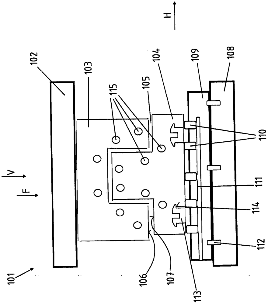
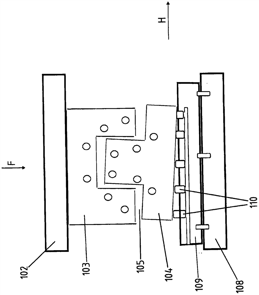
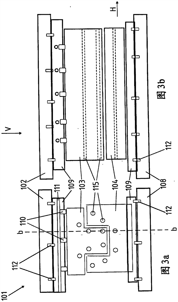
[0034] figure 1 A side cross-sectional view of a press forming die 101 according to the present invention is shown. For this purpose, the stamping tool 101 has a pressure punch 102 , shown from top to bottom in the plane of the drawing, to which an upper die 103 , not shown in detail, is coupled. The stamping force F is applied by the press punch 102 in the vertical direction V, which simultaneously corresponds to the stamping stroke movement, and the upper die 103 and the lower die 104 are closed. Between the upper die 103 and the lower die 104 there remains an inter-die space 105 and a slab not shown in detail in the figure, which, within the scope of the invention, is particularly preferably in full contact with the corresponding mold surfaces 106, 107 . According to the invention it is provided that a tool clamping plate 109 is arranged on the stamping table 108 and that different elastic adjustment elements 110 are arranged between the lower tool 104 and the tool clampi...


PUM


Abstract

The invention relates to a stamping mold (101), which has an upper mold (103) and a lower mold (104), the upper mold and the lower mold can move relatively, and when the stamping mold (101) is closed Between the die (103) and the lower die (104) there is an inter-mold gap (105), characterized in that a die clamping plate (109) is provided on the pressure punch (102) and / or the stamping table (108) An upper mold (103) or a lower mold (104) capable of relative movement relative to the mold clamping plate (109) is supported on the mold clamping plate by inserting at least one elastic adjustment element (110).

Description

technical field [0001] The invention relates to a stamping die with an upper die and a lower die. Background technique [0002] Press forming tools for producing sheet metal shaped components are already known from the prior art. To this end, the slab is placed in a stamping die and then shaped by the relative movement of the upper and lower dies. For this reason, the upper die is usually sunk by means of a pressure punch, and the slab is deformed when the upper die is in contact with the slab and the slab is in contact with the lower die, until the upper die and the lower die are closed, so that when the slab is inserted Under normal circumstances, the gap between the molds is reserved between the upper mold and the lower mold. The formed blank is then finally formed in the interdie space into the component to be produced by stamping. In the case of a press with a plurality of adjacently arranged upper dies, in which case two, three or more blanks can be formed in parall...

Claims


Application Information

Patent Timeline
Patent Type & Authority Patents(China)
IPC IPC(8): B21D37/10B21D37/16B21D22/02
CPCB30B15/06B30B15/061B30B15/064B30B15/067B30B15/245C21D1/673B30B15/007B30B15/026B30B15/068B21D24/02B21D37/04
Inventor G·弗罗斯特O·吕特克迈尔J·克斯特
Owner BENTELER AUTOMOBILTECHNIK GMBH
Why Eureka
Try Eureka