New gas-hydraulic booster cylinder

A technology of gas-liquid booster and booster cylinder, which is applied in the direction of presses, fluid pressure converters, manufacturing tools, etc., and can solve the problems of poor diameter of the working oil chamber and difficulty in further improving the impact force, etc.

Active Publication Date: 2016-05-11
SUZHOU ICOOLMACH EQUIP MFG
View PDF9 Cites 0 Cited by
  • Summary
  • Abstract
  • Description
  • Claims
  • Application Information

AI Technical Summary

Problems solved by technology

[0003] Although the gas-hydraulic booster cylinder in the prior art can achieve an impact force of more than 2kN, it is difficult to obtain the impact force due to the difference in diameter of the working oil chamber, the mechanical force supported by the impact rod on the working piston, and the limitation of the outer diameter of the stamping rod. Further improvement, at the same time, the power stroke only adopts one stroke, which also limits the further improvement of the impact force of the stamping rod

Method used


Image

  • New gas-hydraulic booster cylinder
  • New gas-hydraulic booster cylinder
  • New gas-hydraulic booster cylinder

Examples


Embodiment Construction

[0020] The specific implementation manners of the present invention will be further described in detail below in conjunction with the accompanying drawings and embodiments. The following examples are used to illustrate the present invention, but are not intended to limit the scope of the present invention.

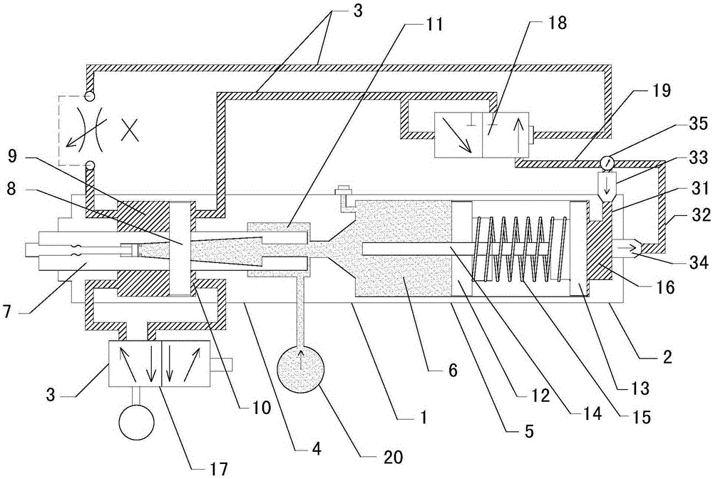
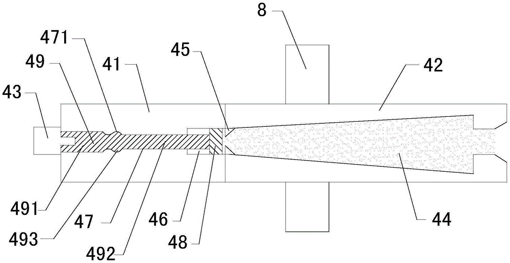
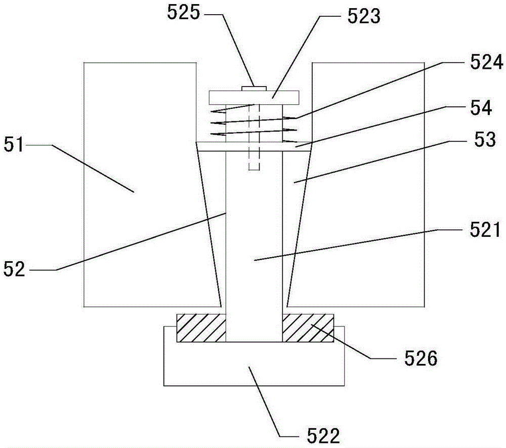
[0021] see Figure 1 to Figure 4 As shown, a new gas-hydraulic booster cylinder includes a hydraulic cylinder 1, a gas cylinder 2 and a gas-liquid conversion circuit 3, wherein the hydraulic cylinder 1 is composed of a fast-forward cylinder 4 and a booster cylinder 5, and the fast-forward cylinder 4 and booster cylinder 5 There is an airtight oil storage chamber 6 between them. A stamping rod 7 is arranged in the fast-forward cylinder 4. There are large cylinders 9 and small cylinders 10 on both sides of the working piston 8 on the stamping rod 7. One side of the stamping rod 7 is the working oil. Cavity 11, booster cylinder 5 is provided with a conversion piston, the con...


PUM


Abstract

The invention relates to a novel pressurized oil-air cylinder which is capable of further improving the stamping force in the condition of the same equipment size through a two-section stroke mode. Work air channels comprise an air inlet channel and an air outlet channel, a high-pressure one-way air valve and a large-flow one-way air valve are arranged on the air inlet channel and the air outlet channel respectively, and a switching valve is arranged at the air inlet channel and air outlet channel connection position. A stamping rod comprises a front rod body, a rear rod body and a stamping head. A secondary stamping oil cavity is formed in the rear rod body, the inner diameter of the secondary stamping oil cavity is decreased from the rear end to the front end, and a piston retaining block is arranged at the front end of the secondary stamping oil cavity. A piston cavity is formed in the rear end of the front rod, a sliding rod cavity is formed in the middle section and the front section of the front rod, a secondary stamping piston is arranged in the piston cavity, an ejection rod is arranged in the sliding rod cavity, and a stamping head is connected with the front end of the ejection rod. The ejection rod comprises a front ejection rod body and a rear ejection rod body, and a clamping block is arranged on the rear ejection rod body. The sliding rod cavity comprises a front sliding rod cavity body and a rear sliding rod cavity body, and a clamping groove is formed in the inner wall of the rear sliding rod cavity body.

Description

technical field [0001] The invention relates to a power drive device used for equipment such as a punching machine, in particular to a novel gas-hydraulic booster cylinder. Background technique [0002] Pneumatic-hydraulic booster cylinder, also known as gas-liquid booster cylinder, is a hydraulic component that combines the advantages of air cylinders and oil cylinders to improve the design, can change the input pressure, and output at a higher pressure; for example, the utility model patent of the Chinese patent publication No. CN2743288Y , which discloses such a gas-hydraulic booster cylinder, which usually includes a hydraulic cylinder, an air cylinder and a gas-liquid conversion circuit, wherein the hydraulic cylinder is composed of a fast-forward cylinder and a booster cylinder, and there is a closed gap between the fast-forward cylinder and the booster cylinder The oil storage chamber and the fast-forward cylinder are equipped with a stamping rod. There are large cyli...

Claims


Application Information

Patent Timeline
Patent Type & Authority Patents(China)
IPC IPC(8): F15B3/00B30B15/16
Inventor 徐明
Owner SUZHOU ICOOLMACH EQUIP MFG
Why Eureka
Try Eureka