
Rotating structure of air gun cylinder head

A rotating structure and cylinder head technology, applied in the field of air guns, can solve the problems of reduced efficiency, troublesome assembly and disassembly, and high requirements for operators

Active Publication Date: 2017-07-11
成都宾森机械工具有限公司
View PDF7 Cites 0 Cited by
  • Summary
  • Abstract
  • Description
  • Claims
  • Application Information

AI Technical Summary

Problems solved by technology

This method is troublesome to assemble and disassemble. Due to the complicated wiring, it is easy to connect the wrong wiring, which reduces the efficiency, and it is easy to collide during the assembly and disassembly process, thus destroying the dynamic balance of the fan blade.
Therefore, this method has higher requirements for operators, and the cost of employment is also higher.
[0004] The second type, although there is no need to remove the stitches, but the cylinder head and handle must be removed to clean the movement
There are many processes, and it is easy to collide with the wind blades

Method used


Image

  • Rotating structure of air gun cylinder head
  • Rotating structure of air gun cylinder head
  • Rotating structure of air gun cylinder head

Examples


Embodiment 1

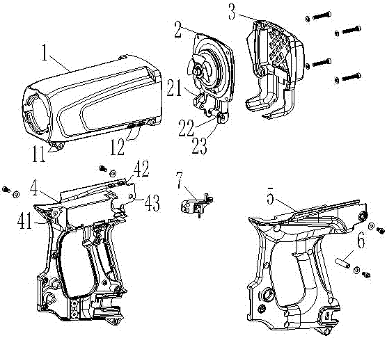
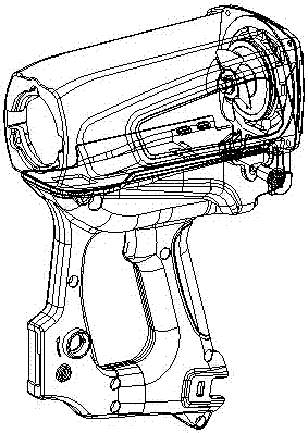
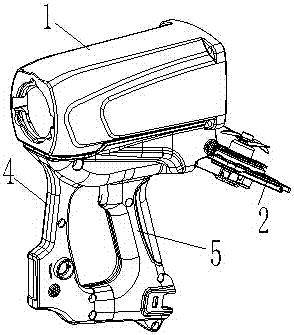
[0032] Such as figure 1 , 2 As shown, a cylinder head rotation structure of an air gun includes a casing 1, a cylinder head 2, a rear cover 3, and a handle. The handle is detachably connected to the bottom of the casing 1, and the rear cover 3 covers the cylinder head 2. And it is detachably connected to the end of the shell 1 together with the cylinder head 2, and the bottom of the cylinder head 2 is connected to the handle in rotation. The core components installed in the shell 1 are as image 3 shown.

[0033] The handlebar is divided into two parts, the right-hand handle 4 and the left-hand handle 5, as Figure 4 , 5 shown. The right-hand handle 4 and the left-hand handle 5 are respectively fixed on both sides of the bottom of the housing 1 , and the bottom of the cylinder head 2 is rotatably connected between the right-hand handle 4 and the left-hand handle 5 .

[0034] A connection hole 11 is provided on both sides of one end of the bottom of the housing 1, and a s...

Embodiment 2

[0038] Such as figure 1 , 2 As shown, a cylinder head rotation structure of an air gun includes a casing 1, a cylinder head 2, a rear cover 3, and a handle. The handle is detachably connected to the bottom of the casing 1, and the rear cover 3 covers the cylinder head 2. And it is detachably connected to the end of the shell 1 together with the cylinder head 2, and the bottom of the cylinder head 2 is connected to the handle in rotation. The core components installed in the shell 1 are as image 3 shown.

[0039] The handlebar is divided into two parts, the right-hand handle 4 and the left-hand handle 5, as Figure 4 , 5 shown. The right-hand handle 4 and the left-hand handle 5 are respectively fixed on both sides of the bottom of the housing 1 , and the bottom of the cylinder head 2 is rotatably connected between the right-hand handle 4 and the left-hand handle 5 .

[0040] A connection hole 11 is provided on both sides of one end of the bottom of the housing 1, and a s...


PUM


Abstract

The invention discloses an air gun cylinder cover rotating structure which comprises a shell, a cylinder cover, a rear cover and a handgrip. The handgrip is detachably connected to the bottom of the shell. The cylinder cover is covered with the rear cover, and the rear cover and the cylinder cover are detachably connected to the end of the shell jointly. The bottom of the cylinder cover is rotatably connected with the handgrip. The air gun cylinder cover rotating structure has the beneficial effects that after the rear cover is detached, the cylinder cover can be opened through rotation, and a core assembly is taken out to be maintained and cleaned without detaching a motor wire, a spark plug wire and a grounding wire which are connected to the cylinder cover; after the core assembly is maintained and cleaned, the cylinder cover is directly screwed and closed, the rear cover is locked, and thus functions can be restored; the whole cleaning process has the advantages that operation is easy and fast, and fan blades are not prone to damage; the technical requirements for operators are low, even an ordinary worker can maintain and clean a tool easily, and the quality can be well guaranteed, so that the labor cost and time cost are greatly reduced.

Description

technical field [0001] The invention relates to the technical field of air guns, in particular to an air gun cylinder cover rotation structure. Background technique [0002] According to different structures, traditional air gun tools have two cleaning methods: [0003] The first one is to disassemble the motor wires, spark plug wires, and ground wires connected to the cylinder head when cleaning, and the movement can only be cleaned after the cylinder head is removed. This method is cumbersome to assemble and disassemble. Due to the complexity of the wiring, it is easy to connect the wrong wiring, which reduces the efficiency, and it is very easy to collide during the assembly and disassembly process, thereby destroying the dynamic balance of the fan blade. Therefore, this method has higher requirements for operators and higher labor costs. [0004] The second type, although there is no need to remove the stitches, the cylinder head and handle must be removed to clean the...

Claims


Application Information

Patent Timeline
Patent Type & Authority Patents(China)
IPC IPC(8): B25C1/04B25C7/00
CPCB25C1/047B25C7/00
Inventor 郭必忠
Owner 成都宾森机械工具有限公司
Learn More