Bitobar flowmeter

A technology of Pitoba flowmeter and flow totalizer, which is applied in the field of flowmeters, can solve the problems of poor pressure taking effect, easy loosening or even falling off, and inaccurate gas flow measurement in pipelines.

Inactive Publication Date: 2016-03-09
LIAONING BITOBAR TECH CO LTD
View PDF6 Cites 1 Cited by
  • Summary
  • Abstract
  • Description
  • Claims
  • Application Information

AI Technical Summary

Problems solved by technology

The Bitobar sensor is the pressure-taking element when the Bitobar flowmeter measures the fluid flow in the pipeline. Its structural composition mainly includes a pressure-taking head and a pressure guiding tube. The pressure guiding tube has an outer tube and an inner tube, and the outer tube and the inner tube are respectively It is connected with a full pressure interface and a static pressure interface. The pressure taking head includes an upper cylindrical joint and a lower section of the pressure taking head body. The lower part of the pressure taking head body has a total pressure hole and a static pressure hole. The full pressure channel and the static pressure channel through which the pressure head is connected with the pressure guide tube to form a Bitobar sensor with its cylindrical joint, the composition of the Bitobar sensor in the above-mentioned prior art is relatively complicated, the pressure head and the pressure guide The production process of the pipe requires high requirements. In addition, when the gas flow rate in the pipe is low, the effect of the pressure head is not good, resulting in inaccurate measurement of the final gas flow in the pipe. At the same time, the Bitoba sensor with the above structure is stable when installed on the pipe Poor resistance, easy to loosen or even fall off when touched by external objects

Method used


Image

  • Bitobar flowmeter
  • Bitobar flowmeter
  • Bitobar flowmeter

Examples


Embodiment Construction

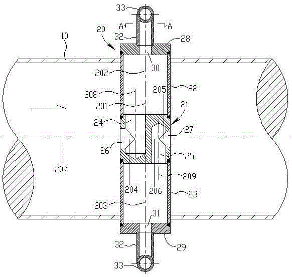
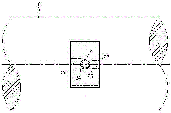
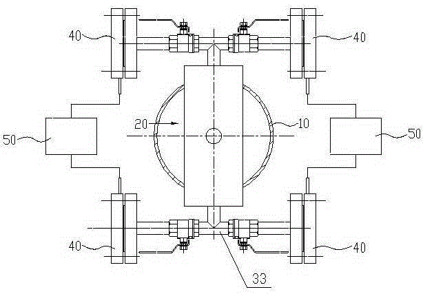
[0012] see figure 1 - image 3 , the Bitoba flowmeter of the present invention includes a sensor 20, a differential pressure transmitter 40 and a flow totalizer 50, and also includes a pipeline section 10, the sensor 20 is inserted into the pipeline section 10, and the sensor 20 includes Straight hexahedral pressure taking head 21 and the full pressure guide square tube 22 and static pressure guide square tube 23 that are sealed and connected to the upper and lower ends of the straight hexahedron shape pressure get head, the full pressure guide square tube 22 and the static pressure guide The square tubes 23 are sealed and fixedly connected with the pipeline section 10 respectively, and the upper end of the full-pressure guiding square tube 22 and the lower end of the static pressure guiding square tube 23 respectively extend out of the pipeline section 10, and the straight hexahedral pressure-taking head 21 is provided with The full pressure semi-hole 24 and the static press...


PUM


Abstract

The invention discloses a Bitobar flowmeter which comprises a pipeline section and a sensor inserted into the pipeline section. The sensor comprises a straight hexahedron-shaped pressure obtaining head, a full-pressure guide square pipe and a static-pressure guide square pipe which are in sealed connection with the upper end and the lower end of the straight hexahedron-shaped pressure obtaining head. The straight hexahedron-shaped pressure obtaining head is provided with a full-pressure half hole and a static-pressure half hole which are formed in the left side and the right side of the upper and lower axes of the straight hexahedron-shaped pressure obtaining head and are communicated with the full-pressure guide square pipe and the static-pressure guide square pipe respectively. The left side and the right side of the straight hexahedron-shaped pressure obtaining head are correspondingly provided with a full-pressure hole and a static-pressure hole which are communicated with the full-pressure half hole and the static-pressure half hole respectively. The upper end of the full-pressure guide square pipe and the lower end the static-pressure guide square pipe are provided with an upper end cover and a lower end cover respectively. The upper end cover and the lower end cover are provided with a full-pressure connector and a static-pressure connector respectively. When low-speed gas flow in a pipeline is measured, large pressure will be produced on the incident flow face of the pressure obtaining head, small pressure is produced on the exit flow face of the pressure obtaining head, the extracted full-pressure and static-pressure difference is large, and therefore a measuring result is more accurate.

Description

technical field [0001] The invention relates to a flowmeter, in particular to a Bitobar flowmeter for measuring gas flow in a pipeline. Background technique [0002] The prior art Bitobar flowmeter for measuring the gas flow in the pipeline is mainly composed of a Bitobar sensor, a differential pressure transmitter and a flow totalizer structurally. The Bitobar flowmeter is simple in composition and easy to install. It is widely used in the measurement of fluid flow in pipelines. The Bitobar sensor is the pressure-taking element when the Bitobar flowmeter measures the fluid flow in the pipeline. Its structural composition mainly includes a pressure-taking head and a pressure guiding tube. The pressure guiding tube has an outer tube and an inner tube, and the outer tube and the inner tube are respectively It is connected with a full pressure interface and a static pressure interface. The pressure taking head includes an upper cylindrical joint and a lower section of the pres...

Claims


Application Information

Patent Timeline
Patent Type & Authority Applications(China)
IPC IPC(8): G01F1/36
CPCG01F1/36
Inventor 王忠辉
Owner LIAONING BITOBAR TECH CO LTD
Why Eureka
Try Eureka