
Verification device for backlight system

A verification device and backlight system technology, which is applied in the field of backlight, can solve the problems of separate verification and trouble of light bars and driving devices

Active Publication Date: 2019-02-01
SHENZHEN TCL NEW-TECH CO LTD
View PDF8 Cites 0 Cited by
  • Summary
  • Abstract
  • Description
  • Claims
  • Application Information

AI Technical Summary

Problems solved by technology

In the prior art, for the verification of the light bar and the driving device, the conventional method is to play the TV signal after the whole machine is assembled, and judge whether the light bar and the driving device are working abnormally by human eyes. The light bar and the driving device are verified separately. Once the assembled TV has a problem with the light bar or the driving device, it can only be repaired or replaced with the corresponding parts, which is troublesome.

Method used


Image

  • Verification device for backlight system
  • Verification device for backlight system
  • Verification device for backlight system

Examples


Embodiment Construction

[0026] The following will clearly and completely describe the technical solutions in the embodiments of the present invention with reference to the accompanying drawings in the embodiments of the present invention. Obviously, the described embodiments are only part of the embodiments of the present invention, not all of them. Based on the embodiments of the present invention, all other embodiments obtained by persons of ordinary skill in the art without creative efforts fall within the protection scope of the present invention.

[0027] It should be noted that all directional indications (such as up, down, left, right, front, back...) in the embodiments of the present invention are only used to explain the relationship between the components in a certain posture (as shown in the accompanying drawings). Relative positional relationship, movement conditions, etc., if the specific posture changes, the directional indication will also change accordingly.

[0028] In addition, the ...


PUM


Abstract

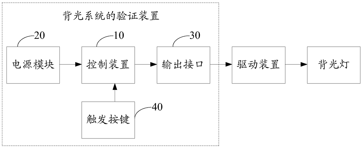
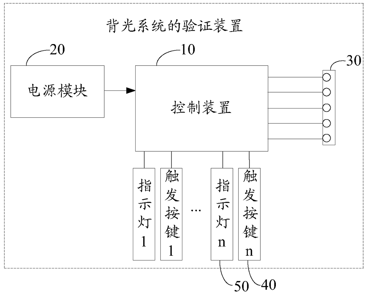
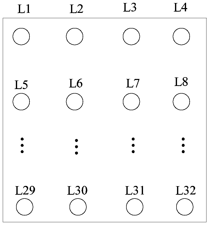
A verification device for a backlight system. The verification device for a backlight system comprises a control device (10), a power supply module (20) supplying power to the control device (10), and output interfaces (30) connected with the control device (10) and used for allowing a driving device of a backlight lamp to be inserted. The control device (10) pre-stores multiple control instructions used for controlling the lighting sequence of matrix backlight lamps. The control device (10) is separately connected with trigger keys (40) for controlling output of the control instructions, and indicator lamps for indicating statuses when the control instructions are outputted correspondingly, wherein when the trigger key (40) corresponding to one control instruction is pressed down, the control device (10) outputs the corresponding control instruction to the driving device of the backlight lamp by means of the output interface (30), thereby enabling the driving device to drive the backlight lamp to display a pattern corresponding to the control instruction. Separate test of a driving device and a backlight lamp can be implemented.

Description

technical field [0001] The invention relates to the field of backlight technology, in particular to a verification device for a backlight system. Background technique [0002] Currently, the direct-lit backlight technology is widely used in various display devices, especially in televisions, because it can realize a local dimming function (LOCAL DIMMING). The so-called local dimming function is to divide the backlights behind the screen into several groups: such as 32 groups, 64 groups, 128 groups, etc., each group consists of several backlights in series, the more groups, the finer the division, the better the effect . The brightness of each group of lights is determined by the brightness of the screen, which can make the display effect better and save energy. This is the basic principle of the local dimming function. [0003] Among them, the local dimming system is divided into the driver and the light bar. The driver part receives the dimming signal provided by the mai...

Claims


Application Information

Patent Timeline
Patent Type & Authority Patents(China)
IPC IPC(8): G09G3/22G09G3/34
CPCG09G3/22G09G3/3406G09G3/34
Inventor 王坚
Owner SHENZHEN TCL NEW-TECH CO LTD
Learn More