Eureka AIR delivers breakthrough ideas for toughest innovation challenges, trusted by R&D personnel around the world.

A testing system and testing method for an optical chip

A testing system and optical chip technology, applied in optical instrument testing, machine/structural component testing, optics, etc., can solve the problem of difficult in/out coupling of optical signals to silicon optical chips, and achieve high process repeatability , the effect of easy replacement

Active Publication Date: 2021-06-29
SHANGHAI XIANFANG SEMICON CO LTD
View PDF15 Cites 0 Cited by
  • Summary
  • Abstract
  • Description
  • Claims
  • Application Information

AI Technical Summary

Problems solved by technology

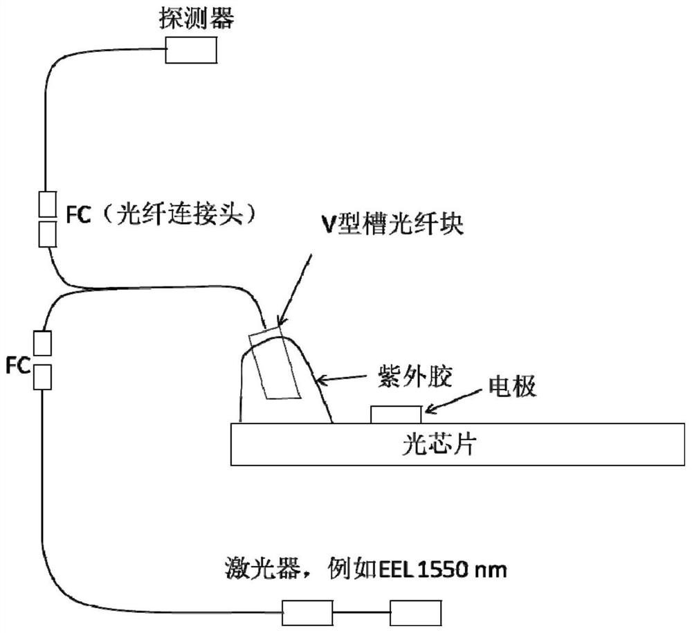
[0005] The present invention aims to solve the problems of high-precision testing of silicon-based optoelectronic chips and the difficulty of in / out coupling of optical signals to silicon-optical chips

Method used


Image

  • A testing system and testing method for an optical chip
  • A testing system and testing method for an optical chip
  • A testing system and testing method for an optical chip

Examples


Embodiment Construction

[0030] In the following description, the present invention is described with reference to various examples. One skilled in the art will recognize, however, that the various embodiments may be practiced without one or more of the specific details, or with other alternative and / or additional methods, materials, or components. In other instances, well-known structures, materials, or operations are not shown or described in detail so as not to obscure aspects of the various embodiments of the invention. Similarly, for purposes of explanation, specific quantities, materials and configurations are set forth in order to provide a thorough understanding of embodiments of the invention. However, the invention may be practiced without these specific details. Furthermore, it should be understood that the various embodiments shown in the drawings are illustrative representations and are not necessarily drawn to scale.

[0031] In this specification, reference to "one embodiment" or "the...


PUM


Abstract

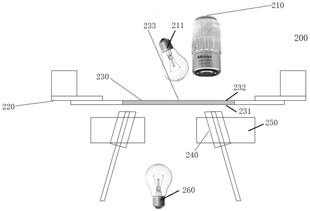
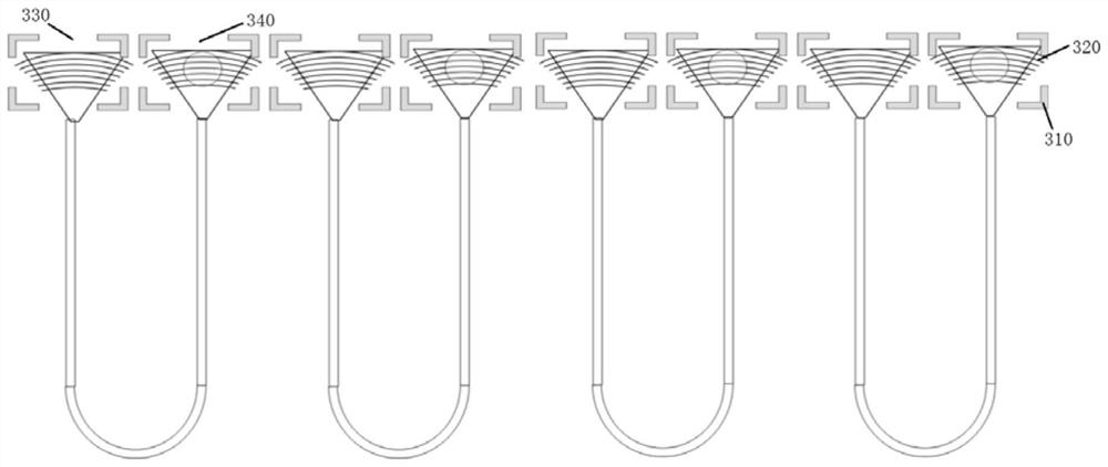
The invention discloses a testing system for an optical chip, comprising: a microscope, the microscope has an objective lens; a chip clamp, the chip clamp is located below the objective lens; an optical fiber coupling block, the optical fiber coupling block is located on the Below the chip fixture; a position adjustment structure, wherein the fiber coupling block is fixed on the position adjustment structure, and the position and angle of the fiber coupling block are adjusted by adjusting the position adjustment structure. Through the disclosed embodiments of the present invention, the grating area of ​​the optical chip can realize multi-channel optical coupling at the same time, the receiving end and the transmitting end can be tested separately, the chip test is convenient to replace, the multi-channel optical fiber can be recycled, and the channels can be assembled and formed at one time, which can realize Batch assembly, high process repeatability.

Description

technical field [0001] The invention relates to the technical field of packaging and testing of optical chips. Specifically, the present invention relates to a testing system and testing method for an optical chip. Background technique [0002] In recent years, due to the rapid development of data centers and cloud computing, a large amount of data needs to be stored and exchanged. Silicon-based photonics has become the preferred solution to this problem due to its unique inherent advantages such as compatibility with CMOS processes and low cost. On the one hand, through the continuous research and development of various enterprises and research institutes, more and more silicon-based photonic devices such as detectors, modulators, waveguides, and gratings have achieved rapid and efficient development. Whether it is a discrete device or a monolithic integrated chip, Its performance can basically meet the current application requirements, but the non-destructive testing of ...

Claims


Application Information

Patent Timeline
Patent Type & Authority Patents(China)
IPC IPC(8): G01R31/28G01M11/00G01N21/84G02B21/00
CPCG01M11/00G01N21/84G01R31/2851G02B21/0004
Inventor 薛海韵
Owner SHANGHAI XIANFANG SEMICON CO LTD
Why Eureka
Eureka Blog
Learn More