Cable bridge stand apparatus with characteristic of convenient indoor angle installation

A bridge and cable technology, applied in the field of cable bridge devices, can solve the problems of dust entry, installation and disassembly, labor-intensive and time-consuming, and poor connection, so as to avoid heat accumulation, avoid dust entry, and achieve the best heat dissipation performance. Effect

Inactive Publication Date: 2016-03-09
南宁市春江电控技术研究所
View PDF6 Cites 1 Cited by
  • Summary
  • Abstract
  • Description
  • Claims
  • Application Information

AI Technical Summary

Problems solved by technology

However, the load-bearing strength of the traditional bridge and the heat dissipation effect of the laid wires or cables are not ideal.
Ordinary bridges are steel plates that are bent and folded into grooves, and then wires and cables are placed in the grooves, and then cover plates are added on them. The bridges with this structure have poor heat dissipation and use more materials, which increases the Increased costs and waste of materials
In addition, the current traditional cable bridge uses a cover plate on the main body of the bridge frame. The cover plate and the main body of the bridge frame are generally connected by bolts. After the main body of the bridge is connected, the seal is not tight, and it is inevitable that dust, moisture, or direct exposure to high temperature will inevitably occur. The cables in the bridge are easily damaged, and the cable bridge cannot protect the cables well. The cable bridge, the side plate and cover plate of the bridge are easily deformed and damaged
[0003] At the same time, when the bridge frame in the prior art is installed at a corner, it is necessary to specially make a corner connecting bridge frame, and the connection between the corner connecting bridge frame and the ordinary bridge frame is relatively loose, which is easy to cause dust to enter, and at the same time increases the difficulty of installation

Method used


Image

  • Cable bridge stand apparatus with characteristic of convenient indoor angle installation
  • Cable bridge stand apparatus with characteristic of convenient indoor angle installation
  • Cable bridge stand apparatus with characteristic of convenient indoor angle installation

Examples


Embodiment Construction

[0020] The preferred embodiments of the present invention will be described in detail below in conjunction with the accompanying drawings, so that the advantages and features of the present invention can be more easily understood by those skilled in the art, so as to define the protection scope of the present invention more clearly.

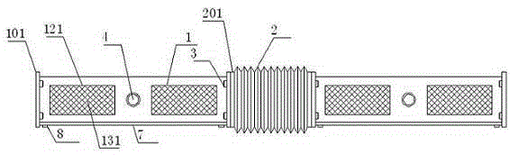
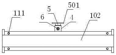
[0021] refer to Figure 1 to Figure 5 A cable tray device that is convenient for indoor angle installation is shown, including several bridge boxes 1, and a folding part 2 connected between two adjacent bridge boxes 1, and the two ends of the bridge box 1 are arranged There is a connecting plate 101, the two ends of the folded part 2 are provided with a first connecting plate 201, a first screw 3 is fitted between the connecting plate 101 and the first connecting plate 201, the top of the bridge box 1 An end portion 4 is provided, and a rotating shaft 5 is fitted in the end portion 4, and the top of the rotating shaft 5 is provided with a mountin...


PUM


Abstract

Disclosed in the invention is a cable bridge stand apparatus with the characteristic of convenient indoor angle installation. The apparatus comprises a plurality of bridge stand boxes and each folding part connected between each two adjacent bridge stand boxes. Connecting plates are arranged at the two ends of the bridge stand boxes; first connecting plates are arranged at the two ends of the folding parts; and first screws are arranged between the connecting plates and the first connecting plates in a cooperative mode. End portions are arranged at the tops of the bridge stand boxes; rotating shafts are arranged inside the end portions in a cooperative mode; and positioning screws are arranged between the end portions and the rotating shafts in a cooperative mode. Circuit repairing and maintenance slots are formed in the front end surfaces of the bridge stand boxes. According to the cable bridge stand apparatus, dust entrance can be effectively avoided; the sealing effect is good; and animals like mice can be prevented from entering the cable bridge stand apparatus effectively, thereby avoiding damages on the cable. When rotating-angle installation is carried out, angle bending can be carried out by using the folding parts; after bending, the good sealing performance still can be maintained. Moreover, the apparatus has the excellent heat radiation performance; accumulation of heat inside the apparatus can be avoided; and aging of the internal cable can be prevented.

Description

technical field [0001] The invention relates to a cable bridge device which is convenient for indoor angle installation. Background technique [0002] At present, in the field of power supply and distribution technology in my country, the bridge is a bracket used to bear wires or cables. However, the load-bearing strength of the traditional bridge and the heat dissipation effect of the laid wires or cables are not ideal. Ordinary bridges are steel plates that are bent and folded into grooves, and then wires and cables are placed in the grooves, and then cover plates are added on them. The bridges with this structure have poor heat dissipation and use more materials, which increases the Increased costs and waste of materials. In addition, the current traditional cable bridge uses a cover plate on the main body of the bridge frame. The cover plate and the main body of the bridge frame are generally connected by bolts. After the main body of the bridge is connected, the seal...

Claims


Application Information

Patent Timeline
Patent Type & Authority Applications(China)
IPC IPC(8): H02G3/04
CPCH02G3/0406H02G3/0468
Inventor 卢嘉兴
Owner 南宁市春江电控技术研究所
Why Eureka
Try Eureka