

Synthesis of hydrogen bis(fluorosulfonyl)imide
A fluorosulfonyl and chlorosulfonyl technology, which is applied in the field of bis(fluorosulfonyl)imide synthesis, can solve the problems of difficult control of industrial scale, toxicity of arsenic trifluoride, and low yield
- Summary
- Abstract
- Description
- Claims
- Application Information
AI Technical Summary
Problems solved by technology
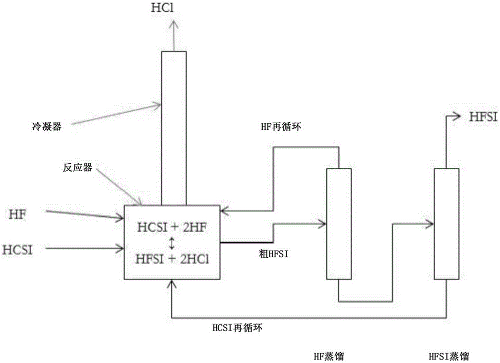
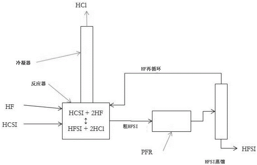
Method used
Image


Examples
Embodiment 1
[0040] Example 1: A 120 mL PFA reactor with PFA coated thermocouple, PTFE coated magnetic stir bar and PTFE zeolite was charged with 47.4 g (0.221 mol) HCSI. The reactor was connected to a condenser consisting of vertical 60 mm long PTFE tubing with an inner diameter of 9.5 mm. The exterior of the condenser tubes was lined with conduits containing a mixture of dry ice and methanol. The upper part of the condenser was purged with dry argon which carried the gas from the upper part of the condenser to the alkaline scrubber before venting. A reactor inlet is provided to deliver gaseous HF into the system which will condense in the condenser and drop into the reactor. The reactor was immersed in a heated and stirred oil bath. A metered addition of 8.86 g (0.443 mol) of HF was required to convert HCSI to HFSI. Add HF incrementally. The first addition amount was 3.5 g (0.175 mol) HF, and the solution was boiled and refluxed at 36.5°C. The ambient pressure is 82kPa. No change i...
Embodiment 2
[0041] Example 2: Using the same reactor system as described in Example 1, 51.768 g (0.242 mol) of HCSI was charged to the reactor. No bismuth species or PTFE zeolites are added. The reactor was heated to 100°C and HF was added portionwise while trying to keep the reaction temperature close to 100°C. The reactor temperature ranged between 61 °C and 110 °C between each HF addition, and the amount of HF added was not recorded. After several small additions of HF over a period of 4.5 hours, the temperature stabilized at 85°C. The reactor was cooled and crystallization started at 12.2°C. The condenser was heated to room temperature and the reactor was reheated to about 115° C. for 30 minutes while argon was flowing through the reactor to remove excess HF from the liquid product. The contents were then cooled and detected to have a melting point of 18.6°C. The product weighed 42.798 g, which corresponds to 0.236 mol and 98% HFSL. A sample was collected and analyzed by ion chro...
Embodiment 3
[0042] Example 3: Using the same reactor system as described in Example 1, 51.184 g (0.239 mol) of HCSI and 2.86 g (0.00907 mol) of BiCl 3 Fill the reactor. The reactor was heated to 100°C and HF was added slowly while trying to keep the reaction temperature close to 100°C. The reaction temperature range is between 90 and 110°C. The reaction temperature stabilized at 96°C over a period of 3.5 hours and after several small additions of HF. The condenser was warmed to room temperature and the reactor was heated to 100° C. under flowing argon for 1.25 hours to remove excess HF. Then, the reactor was cooled and a melting point of 9.2°C was detected. The product weighed 45.261 g, which corresponds to a 99% yield including BiCl 3 Convert to BiF 3 . A liquid product sample was taken and analyzed by ion chromatography, which indicated close to 100% FSI - and about 200ppm w Cl - and 600ppm w f - .
PUM
| Property | Measurement | Unit |
|---|---|---|
| boiling point | aaaaa | aaaaa |
| melting point | aaaaa | aaaaa |
| melting point | aaaaa | aaaaa |
Abstract
Description
Claims
Application Information