
Hydraulic tensioning clamp

A technology of tightening clamps and hydraulic pressure, applied in the field of clamps for disc parts, can solve the problems of large ovality, thin positioning surface wall, easily deformed disc parts, etc., to achieve uniform force, stable precision, and lower production costs. Effect

Inactive Publication Date: 2016-03-16
CHENGDU ENGINE GROUP
View PDF6 Cites 1 Cited by
  • Summary
  • Abstract
  • Description
  • Claims
  • Application Information

AI Technical Summary

Problems solved by technology

[0003] The purpose of the present invention is to overcome the deficiencies of the prior art and provide a hydraulic tensioning fixture to solve the processing problems of disc parts with large ellipticity, thin positioning surface, easy deformation and no pressing surface

Method used


Image

  • Hydraulic tensioning clamp
  • Hydraulic tensioning clamp
  • Hydraulic tensioning clamp

Examples


Embodiment Construction

[0019] The following examples will further illustrate the hydraulic tensioning clamp and its usage method of the present invention.

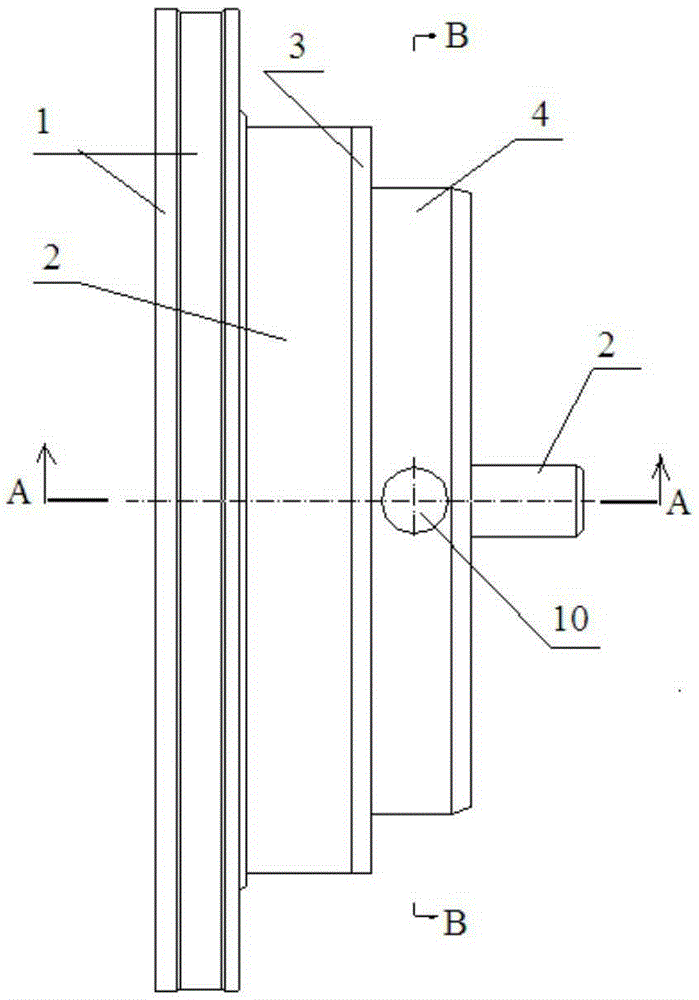
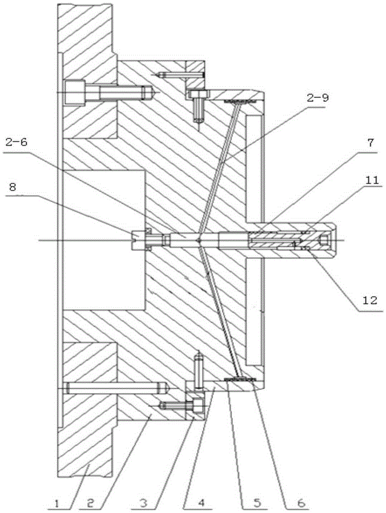
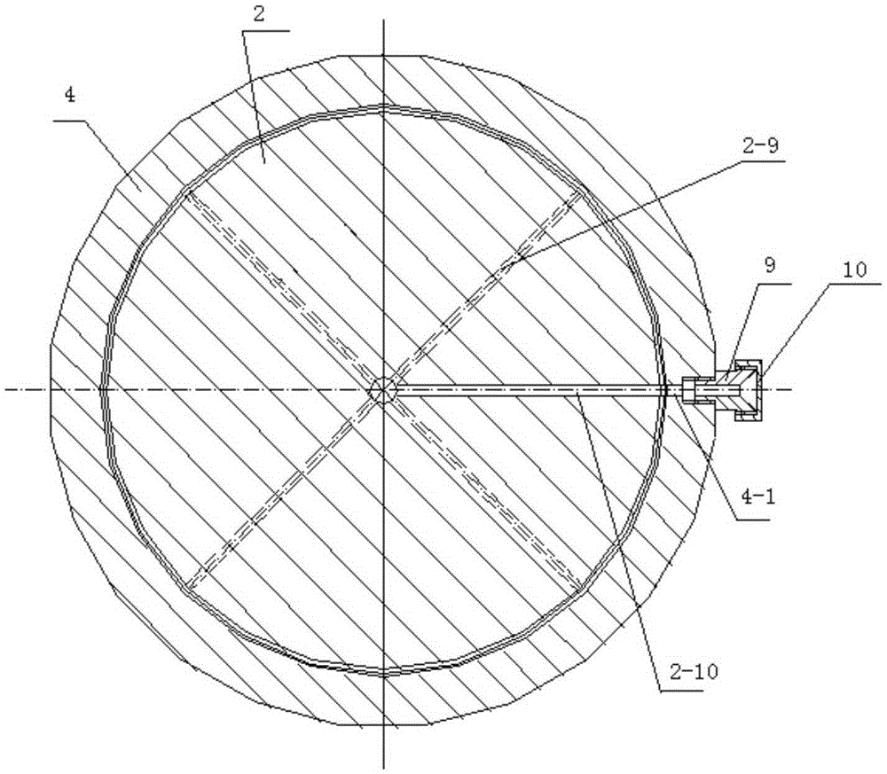
[0020] In this embodiment, the hydraulic tensioning fixture such as figure 1 , figure 2 , image 3 As shown, it includes a base 1 , a main body 2 , a support ring 3 , a positioning sleeve 4 , a spacer ring 5 , a sealing ring 6 , a screw plug 7 , an exhaust screw 8 , an oil cup 9 and a screw cover 10 .

[0021] The base 1 is as figure 2 As shown, the end faces of the left and right ends of the base are parallel to each other, and a central hole combined with the main body is provided, and the center line of the center hole is perpendicular to the end faces of the left and right ends of the base. The subject 2 as Figure 4 As shown, it is a stepped cylindrical platform, and from the left end to the right end of the stepped cylindrical platform are the first circular platform section 2-1, the second circular platform section 2-2, the third ci...


PUM


Abstract

A hydraulic tensioning clamp comprises a base, a main body, a supporting ring, a positioning sleeve, a spacer ring, a seal ring, a plug screw, an exhaust screw, an oil cup and a blind nut, wherein a first circular truncated cone section of the main body is mounted in a center hole of the base; a second circular truncated cone section of the main body is fixedly connected with the base; the spacer rings and the seal rings are mounted in ring grooves in the cylindrical surface of a third circular truncated cone section of the main body; the seal ring is close to one side of a fourth circular truncated cone section of the main body; the positioning sleeve sleeves the third circular truncated cone section of the main body and is fixedly connected with the third circular truncated cone section; an oil filler hole formed in the wall of the positioning sleeve is connected with an oil inlet in the cylindrical surface of the third circular truncated cone section; the supporting ring sleeves the positioning sleeve, is clung to the second circular truncated cone section of the main body, and is fixedly connected with the second circular truncated cone section of the main body; an oil outlet section of the oil cup is inserted in the oil filler hole in the wall of the positioning sleeve; the blind nut and the body of the oil cup are connected; the plug screw is mounted at a plug screw mounting section of a through hole in the center part of the main body; and the exhaust screw is mounted at a screw mounting section of the through hole in the center part of the main body.

Description

technical field [0001] The invention belongs to the field of fixtures for processing parts, and in particular relates to a fixture for processing disc parts with large ellipticity, thin positioning surface, easy deformation and no pressing surface. Background technique [0002] For disc parts with large ellipticity, poor positioning accuracy, thin positioning surface, easy deformation and no pressing surface, if conventional mechanical clamping and pressing fixtures are used, they cannot meet the processing accuracy requirements at all, and even cannot be processed. It is a block-type fixture driven by mechanical force, and it is difficult to guarantee the processing quality. Due to the uniform force exerted by oil pressure tensioning, it is very necessary to develop an oil pressure tensioning fixture. Contents of the invention [0003] The purpose of the present invention is to overcome the deficiencies of the prior art and provide a hydraulic tensioning fixture to solve...

Claims


Application Information

Patent Timeline
Patent Type & Authority Applications(China)
IPC IPC(8): B23B31/40
CPCB23B31/40
Inventor 杨莉玫刘建乔惠芳姜宝华罗仁俊李婧李海宁胡彦彬
Owner CHENGDU ENGINE GROUP
Learn More