Light source and light beam scanning unit

a scanning unit and light source technology, applied in the direction of mountings, instruments, printing, etc., can solve the problems of insufficient durability of the driving motor, inability to meet the requirements of the application, and unstable holding conditions, so as to reduce deviation, improve the effect of image quality and low cos

Active Publication Date: 2007-11-13
RICOH KK
View PDF10 Cites 14 Cited by
  • Summary
  • Abstract
  • Description
  • Claims
  • Application Information

AI Technical Summary

Benefits of technology

[0043]Accordingly, it is an object of the present disclosure to provide an improved multiple-beam light source for laser beam scanning unit, having most, if not all, of the advantages and features of similar employed systems, while eliminating many of the aforementioned disadvantages.
[00

Problems solved by technology

This method, however, appears to fall short of offering satisfactory solutions to several points which follow.
This may result in slant-abutting as shown in FIG. 17, in which the collimator lens 104 is held by being in contact with only two locations but not in a linear manner (denoted by the mark ‘•’), thereby giving rise to rather unstable holding conditions.
However, several difficulties are encountered such as insufficient durability of the driving motor, undue noise, vibration, and/or speed of laser beam modulation with respect to the method (i), and the need for a light source unit emanating multiple laser beams with the method (ii).
Such semiconductor laser array, however, is rather expensive for practical application at present since it is difficult to increase the channels for the reasons of fabrication process, remove undue effects from thermal and electrical cross-talk, and materialize shorter emission wavelengths.
In addition, present market price per unit channel of the semiconductor laser array rather increases with the increase of the number of light emitting points in a package.
Namely, if the deviation in the relative positio

Method used


Image

  • Light source and light beam scanning unit
  • Light source and light beam scanning unit
  • Light source and light beam scanning unit

Examples


first embodiment

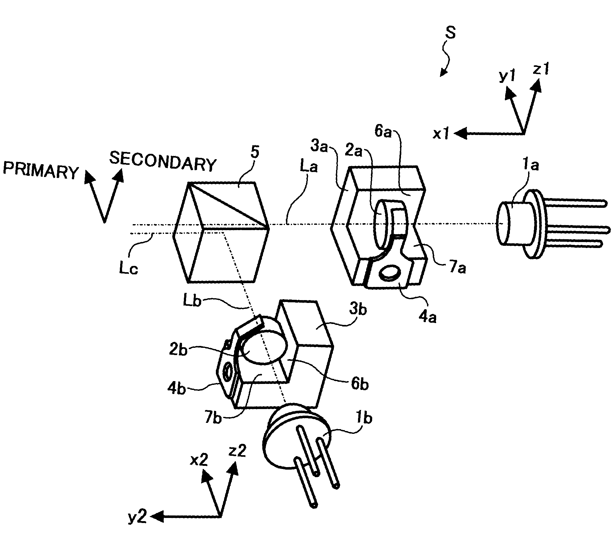
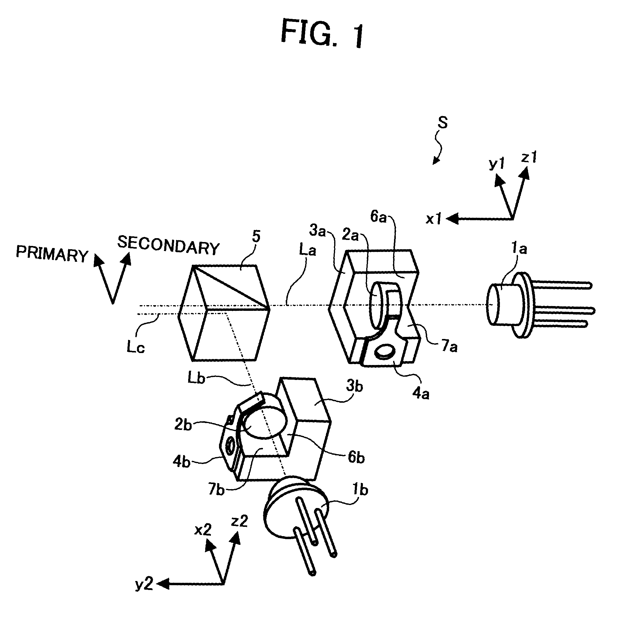
[0071]FIG. 1 is a perspective view illustrating the basic structure of the light source unit disclosed herein;

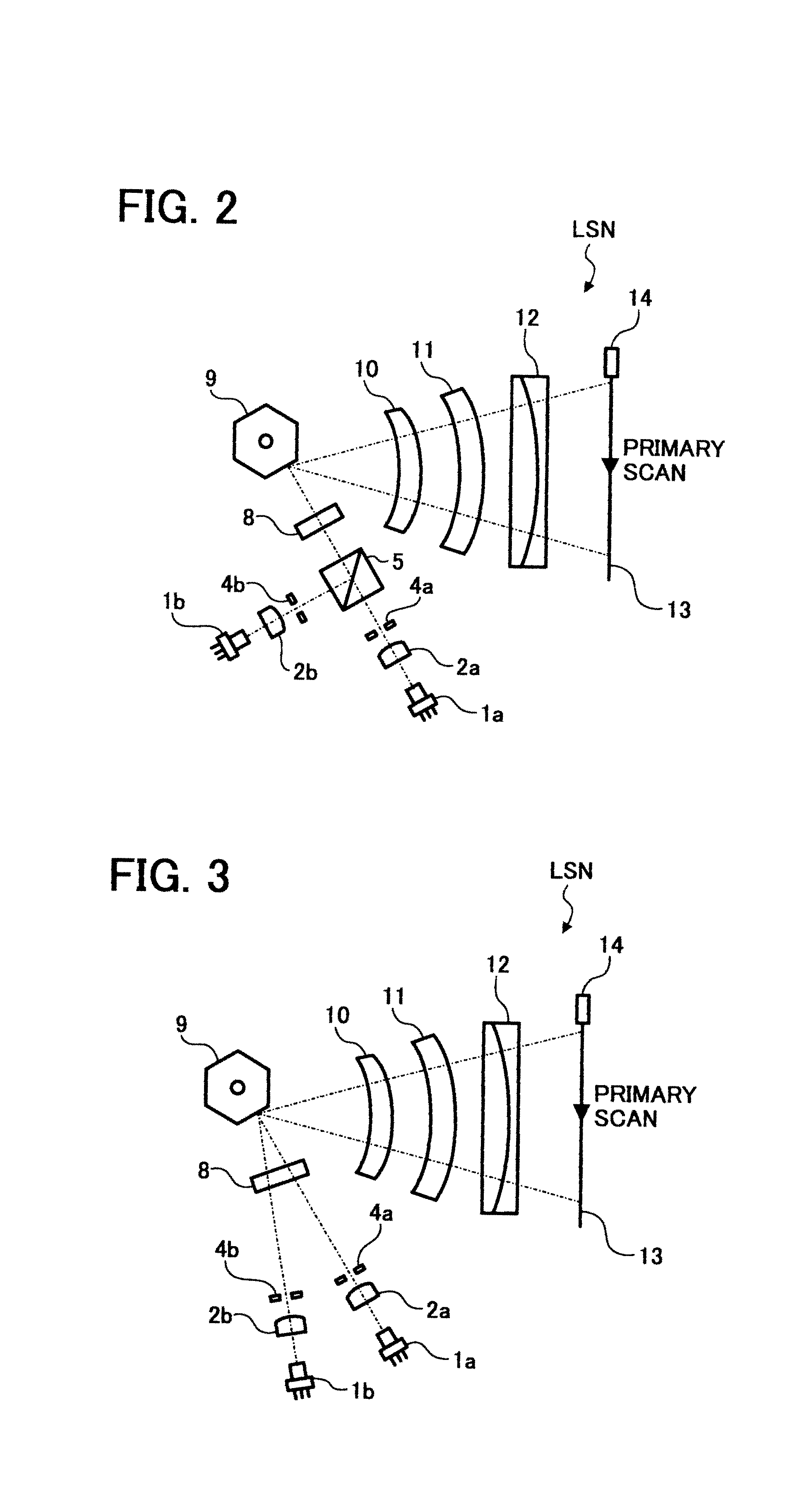
[0072]FIG. 2 illustrates a structure of the light beam scanning system into which the light source unit is suitably incorporated;

[0073]FIG. 3 illustrates a further structure of the light beam scanning system, in which, in place of the use of the beam synthesis prism, two light beams are brought to come across on the mirror face of the scanner so as to carry out beam synthesis and subsequent scanning;

second embodiment

[0074]FIG. 4 is a perspective view illustrating the basic structure of the light source unit S disclosed herein;

third embodiment

[0075]FIG. 5 is a frontal perspective view of the light source unit disclosed herein;

[0076]FIG. 6 is a rear perspective view of the light source unit according to a third embodiment disclosed herein;

[0077]FIG. 7 is an enlarged view of the encircled portion II of the structure of FIG. 5;

[0078]FIG. 8 is a cross-sectional view taken along the line III-III of the structure of FIG. 5;


PUM


Abstract

Light source and light beam scanning units with reduced deviation of beam positions over time and ambient conditions, in use for image forming apparatuses. In the light source unit for emanating light beams, including a plurality of LEDs and coupling lenses each corresponding to the LEDs, there are provided lens holders having two supporting faces aligned approximately parallel to the optical axes of the coupling lenses, elastic members for abutting the coupling lenses by pressing the side portions thereof onto the supporting faces, light source support members for holding LEDs corresponding to the coupling lenses, and bolts for fixing the light source support members. Following the proper adjustment of the position of the lens holder in the vertical direction with respect to the optical axes of the coupling lenses, the light source support members is fixed onto lens holder by bolts.

Description

BACKGROUND[0001]1. Field[0002]The present invention relates to light source and light beam scanning units in use for image recording systems such as a laser printer, digital duplication machine, facsimile apparatus and other similar systems.[0003]2. Discussion of the Background[0004]In many recent developments of digital duplication machines, laser printers and facsimile apparatuses, more attention has been focused on the increase in speed and image quality of information recording, among others. In order to materialize such improved capabilities, it is desirable for light source and light beam scanning units to have high-precision and stability of aligned light beam axes, ease of adjustment, and multiple-beam scanning capability.[0005]The light source and scanning unit generally includes at least a semiconductor laser device as light source, and coupling lenses for coupling the light beams emanated from the source by properly transmitting to the following optical units as a paralle...

Claims


Application Information

Patent Timeline
IPC IPC(8): B41J27/00B41J2/44G02B7/02G02B26/10H04N1/113
CPCG02B7/026
Inventor OHSUGI, TOMOYA
Owner RICOH KK
Why Eureka
Try Eureka