Complete-sequence iron core lamination robot gripper

A robotic gripper and iron core lamination technology, applied in manipulators, chucks, manufacturing tools, etc., can solve problems such as poor performance, low efficiency, and iron core rust, and avoid low efficiency, high automation, and compact layout. Effect

Active Publication Date: 2016-03-16
WUXI PUTIAN IRON CORE CO LTD
View PDF5 Cites 13 Cited by
  • Summary
  • Abstract
  • Description
  • Claims
  • Application Information

AI Technical Summary

Problems solved by technology

[0003] In view of the above problems, the present invention provides a full-sequence iron core lamination robot gripper, which can be used to r

Method used


Image

  • Complete-sequence iron core lamination robot gripper

Examples


Embodiment Construction

[0011] The specific embodiments of the present invention will be further described below in conjunction with the accompanying drawings.

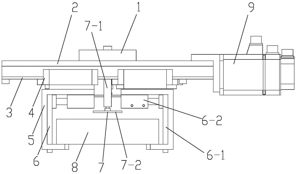
[0012] figure 1 Among them, including interface 1, top plate 2, slide rail 3, slider 4, clip teeth 5, limit device 6, limit plate 6-1, limit cylinder 6-2, lifting device 7, lift cylinder 7-1, Lifting pressure head 7-2, silicon steel sheet 8, motor 9, etc.

[0013] like figure 1 As shown, the present invention is a full-sequence core lamination robot gripper, including a top plate 2, an interface 1 for connecting a robot arm is provided on the top of the top plate 2, a slide rail 3 is provided on the lower surface of the top plate 2, and a screw rod is provided in the middle of the slide rail. Two sliders 4 are arranged on the slide rail 3, and each slider 4 is fixedly connected with a clamping tooth 5, and a motor 9 is installed at the end of the top plate 2, and the output end of the motor 9 is connected with the screw rod, and the screw ...


PUM


Abstract

The invention belongs to the technical field of iron core production equipment and relates to a complete-sequence iron core lamination robot gripper which comprises a top plate, wherein a connector for being connected with an arm of a robot is arranged at the top part of the top plate; a slide rail is arranged on the lower surface of the top plate; a screw rod is arranged at the middle part of the slide rail; two sliding blocks are arranged on the slide rail and fixedly connected with two clamping teeth respectively; a motor is installed at the end part of the top plate; the output end of the motor is connected with the screw rod; the screw rod drives the two sliding blocks to move towards opposite directions; and a lifting device is arranged between the two clamping teeth. The complete-sequence iron core lamination robot gripper has compact, reasonable and efficient layout, can efficiently complete iron core lamination work with high quality, is high in automation degree, improves the production efficiency, solves the problem about low efficiency, poor performance and rusted iron cores caused by artificial lamination, improves the production efficiency and the quality of a product and reduces used persons.

Description

technical field [0001] The invention belongs to the technical field of iron core production equipment, and relates to a full-sequence iron core lamination robot gripper. Background technique [0002] In the prior art, two operators are required to cooperate simultaneously to lift the silicon steel sheets and stack them together. The labor intensity is high and the efficiency is low. Due to the low positioning accuracy of the personnel during the stacking process, each stack has a certain thickness. Finally, the lamination operation needs to be stopped, and the lamination accuracy should be adjusted by tapping the end face of the iron core with a hammer. This operation will increase the loss of the silicon steel sheet; in addition, because the main component of the silicon steel sheet is iron, the operator's hand is in contact with the silicon steel sheet Finally, there will be hand sweat remaining on the silicon steel sheet, which will cause the silicon steel sheet to rust a...

Claims


Application Information

Patent Timeline
IPC IPC(8): B25J15/08
Inventor 蔡子祥张聪闫成亮魏龙潘永前王向阳吴世东王士东
Owner WUXI PUTIAN IRON CORE CO LTD
Why Eureka
Try Eureka