
Gas collector

A collector and gas technology, applied in gas discharge, mining equipment, earthwork drilling and mining, etc., can solve problems such as unsatisfactory results, immaturity, and large engineering volume

Inactive Publication Date: 2018-06-22
李昆
View PDF9 Cites 0 Cited by
  • Summary
  • Abstract
  • Description
  • Claims
  • Application Information

AI Technical Summary

Problems solved by technology

On the one hand, the existing secondary sealing technology is immature and the effect is not ideal
On the other hand, the above-mentioned remedial measures are quite troublesome and the amount of work is huge under the situation that there are many boreholes

Method used


Image

  • Gas collector
  • Gas collector
  • Gas collector

Examples


Embodiment Construction

[0023] The present invention will be described in further detail below through specific embodiments and in conjunction with the accompanying drawings.

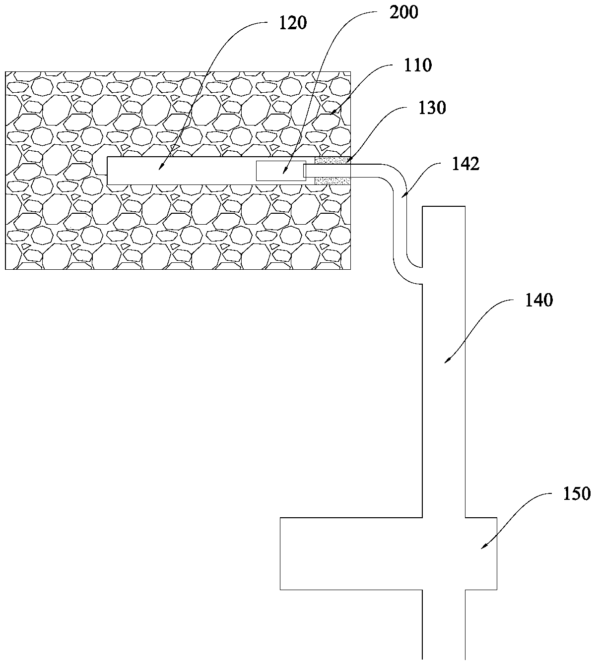
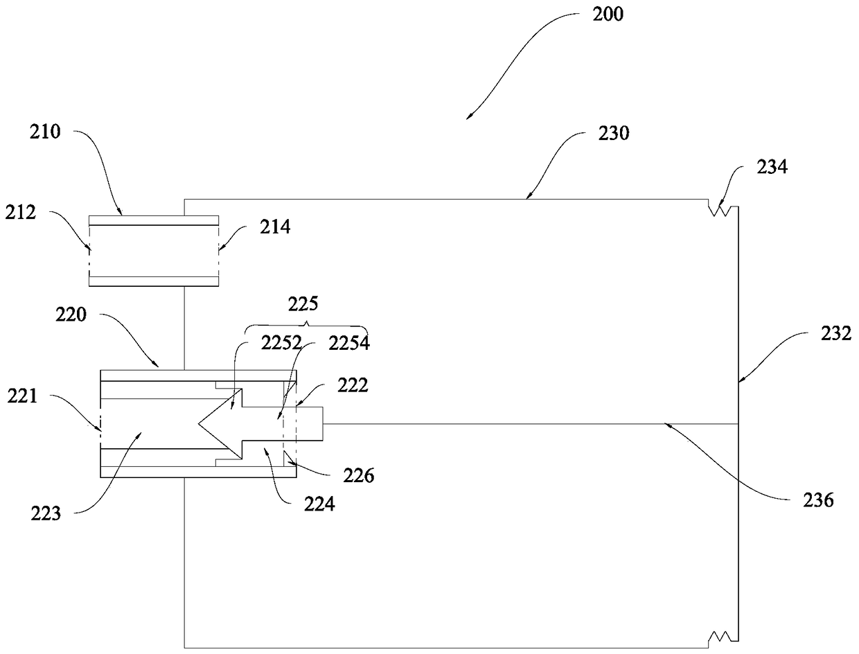
[0024] refer to figure 2 , Figure 3-A and Figure 3-B The gas collector 200 provided in this specific embodiment is placed in the coal seam borehole 120 of a mine where gas protrudes from a low-permeability coal seam. The gas collector 200 may include: an air intake valve 210 , a negative pressure valve 220 and a bottle body 230 . Both the air intake valve 210 and the negative pressure valve 220 are disposed on one side of the bottle body 230 . The air inlet valve 210 and the negative pressure valve 220 can be arranged on the same side of the bottle body 230 or on different sides of the bottle body 230 . In this specific embodiment, preferably, the air intake valve 210 and the negative pressure valve 220 are arranged on the same side of the bottle body 230 .

[0025] In an implementation manner of this specific embodime...


PUM


Abstract

The invention provides a gas collector comprising an inlet valve, a negative pressure valve and a bottle body. The inlet valve and the negative pressure valve are arranged on the bottle body. The bottle body is provided with a movable component opposite to the negative pressure valve. The movable component and the bottle body are connected together via the flexible seal material. The negative pressure valve and a gas main collecting pipeline are in communication with each other and the negative pressure valve is composed of a negative pressure bulkhead. The movable component is provided with a connecting piece and the connecting piece connects the movable component with the negative pressure bulkhead. The gas enters the bottle body via the inlet valve so as to drive the movable component to move towards one side that is far away from the negative pressure valve. The movable component drives the negative pressure bulkhead to move so as to turn on the negative pressure valve through the connecting piece. In this way, the gas in the bottle body enters the gas main collecting pipeline via the negative pressure valve. The concentration of the gas extracted by the above gas collector is high.

Description

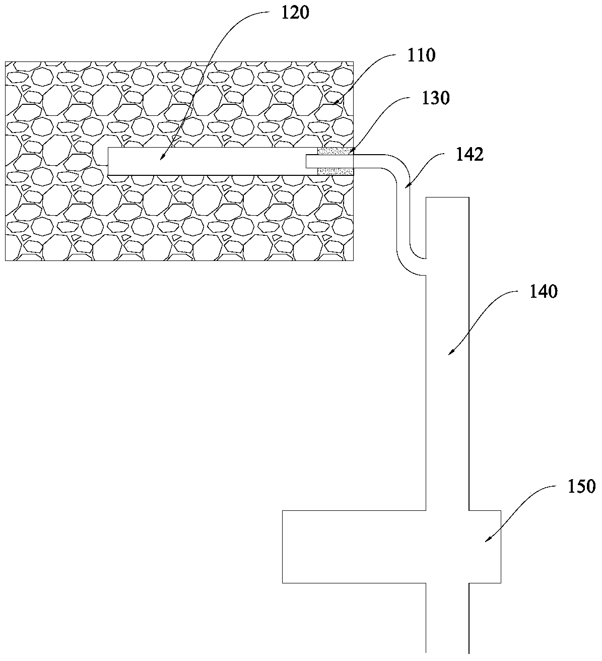
technical field [0001] The invention relates to the technical field of gas drainage, in particular to a gas collector. Background technique [0002] In order to reduce and eliminate the threat of mine gas to coal mine safety production, the method of using the negative pressure caused by mechanical equipment and special pipelines to pump out the gas existing or released in the coal seam and transport it to the ground or other safe places is called gas drainage. According to statistics, at present, there are many mines with gas outbursts in low-permeability coal seams in domestic mines. figure 1 The gas drainage device shown is used for drainage. The specific method is to first drill a borehole 120 in the coal seam 110, place a branch collection pipeline 142 on the main gas collection pipeline 140 in the borehole 120, and use the sealing slurry 130 to seal the borehole 120. Sealing. Then, the gas extraction pump 150 is turned on to generate a negative pressure in the boreh...

Claims


Application Information

Patent Timeline
Patent Type & Authority Patents(China)
IPC IPC(8): E21F7/00
CPCE21F7/00
Inventor 李昆
Owner 李昆
Learn More