
Remote sensing image alteration detection method

A change detection and remote sensing image technology, applied in image enhancement, image analysis, image data processing and other directions, can solve the problem of low accuracy, sensitivity to noise and its outliers, and complex high-resolution image detection environment. The lack of target prior information and other problems, to achieve the effect of high accuracy and robust change detection results.

Active Publication Date: 2016-03-16
HOHAI UNIV
View PDF5 Cites 25 Cited by
  • Summary
  • Abstract
  • Description
  • Claims
  • Application Information

AI Technical Summary

Problems solved by technology

In this type of technology, the disadvantage of using FCM is that it is only suitable for spherical or ellipsoidal clustering, and is extremely sensitive to noise and its outlier (Outlier)
In addition, only the magnitude of the change vector is used, so that the original multispectral information is not fully mined, not robust enough, and the accuracy is not high
[0004] In response to the above problems, many scholars have tried to solve them by adding different spatial neighborhood constraints to the FCM objective function, but the complexity of the high-resolution image detection environment and the lack of prior information of the target have led to certain limitations in these algorithms. limitations, the accuracy is not high

Method used


Image

  • Remote sensing image alteration detection method
  • Remote sensing image alteration detection method
  • Remote sensing image alteration detection method

Examples


Embodiment Construction

[0020] The following will clearly and completely describe the technical solutions in the embodiments of the present invention with reference to the accompanying drawings in the embodiments of the present invention. Obviously, the described embodiments are only some, not all, embodiments of the present invention. Based on the embodiments of the present invention, all other embodiments obtained by persons of ordinary skill in the art without creative efforts fall within the protection scope of the present invention.

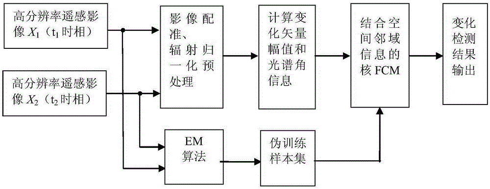
[0021] figure 1 It is a flow diagram of an embodiment of the remote sensing image change detection method provided by the present invention. The present invention is a multi-temporal remote sensing image change detection method, which is mainly applicable to high-resolution optical remote sensing images, such as figure 1 Shown, the present invention comprises steps:

[0022] S101. Obtain two-temporal high-resolution optical remote sensing image X 1 and x 2 .

...


PUM


Abstract

The invention discloses a remote sensing image alteration detection method comprising the steps that two time phase high-resolution optical remote sensing images X1 and X2 are obtained; image registration is performed on X1 and X2; radiation normalization correction is performed on X1 and X2 by utilizing a multivariate alteration detection method; alteration vector amplitude XM and spectral angle information XSA are respectively calculated according to X1 and X2 after radiation normalization correction; an optimal segmentation threshold T is calculated by utilizing the Bayes theory and an expectation maximization algorithm according to the XM; a pseudo training sample area is selected according to T and XM; XM and XSA are combined to act as input of a core FCM, and optimal model parameter value selection is performed on a core FCM combining spatial neighborhood information model according to the pseudo training sample area; and the alteration area and the non-alteration area of the optical remote sensing images are determined by adopting the method of core FCM combining spatial neighborhood information according to the selected optimal model parameter values. The remote sensing image alteration detection method is more robust and higher in precision.

Description

technical field [0001] The invention relates to the technical field of remote sensing image change detection, in particular to a remote sensing image change detection method. Background technique [0002] With the continuous accumulation of multi-temporal high-resolution remote sensing data and the successive establishment of spatial databases, how to extract and detect change information from these remote sensing data has become an important research topic in remote sensing science and geographic information science. According to remote sensing images of different time phases in the same area, dynamic information such as cities and environments can be extracted to provide scientific decision-making basis for resource management and planning, environmental protection and other departments. my country's "Twelfth Five-Year Plan" will increase and expand the implementation of high-resolution earth observation projects that have been launched during the "Eleventh Five-Year Plan"...

Claims


Application Information

Patent Timeline
IPC IPC(8): G06T7/00G06K9/62
CPCG06T2207/10032G06T2207/10004G06F18/2321
Inventor 石爱业高桂荣
Owner HOHAI UNIV
Learn More