Method for controlling a DC/DC voltage step-down converter

A step-down converter, output voltage technology, applied in battery/battery traction, control/regulation system, output power conversion device, etc. Effect

Active Publication Date: 2016-03-16
VTESCO TECH GMBH
View PDF5 Cites 0 Cited by
  • Summary
  • Abstract
  • Description
  • Claims
  • Application Information

AI Technical Summary

Problems solved by technology

output voltage V S This increase of can not be controlled by the regulation switch 14 in blocking state

Method used


Image

  • Method for controlling a DC/DC voltage step-down converter
  • Method for controlling a DC/DC voltage step-down converter
  • Method for controlling a DC/DC voltage step-down converter

Examples


Embodiment Construction

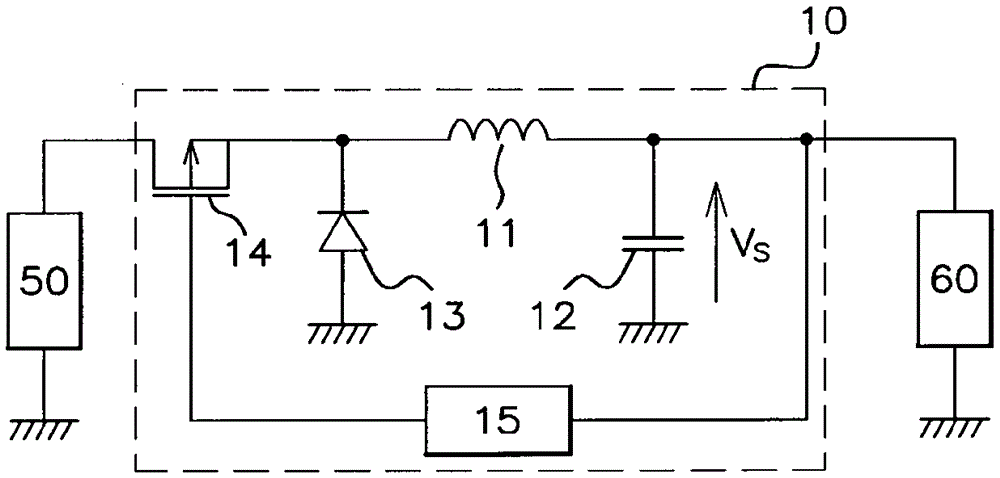
[0046] image 3 An implementation example of the DC / DC step-down converter 20 is shown.

[0047] The buck converter 20 is implemented for supplying an output voltage V having a regulated value from a power source 50 to the terminals of a load 60 S . In the ensuing description, in a non-limiting manner, in the case of a buck converter 20 installed in a motor vehicle, the power source 50 is, for example, the battery of the motor vehicle, or a voltage regulator connected to said battery ,etc. Load 60 is, for example, a microcontroller of the electronic computer of the motor vehicle.

[0048] Depend on image 3 The illustrated buck converter 20 comprises an inductive component 21 one terminal of which is connected to a capacitive component 22 at the output of the buck converter 20 . More particularly, capacitive component 22 includes two terminals, one of which is connected to inductive component 21 and the other of which is connected to electrical ground.

[0049] The other...


PUM


Abstract

The present invention relates to a method for controlling a voltage step-down converter (20) comprising an inductive component (21), one terminal of which is connected to an electricity source (50) by a regulating switch (24), and the other terminal of which is connected to a capacitive component (22), the output voltage of the voltage step-down converter being regulated by alternating connection intervals, during which the regulating switch is in an on state, with disconnection intervals, during which said regulating switch is in an off state, the regulating switch being switched from the on state to the off state when the value of the output voltage reaches a disconnection threshold. The value of said disconnection threshold varies, decreasing progressively during each connection interval, starting from a maximum value of said disconnection threshold.

Description

technical field [0001] The present invention is in the field of direct voltage / direct voltage converters, known as "DC / DC converters", and more particularly relates to methods for operating DC / DC step-down converters, known as "buck converters". A method in which the buck converter is used to supply an output voltage having a regulated value to a load terminal. Background technique [0002] There are many applications for buck converters. In particular, they are used in motor vehicles for reducing the voltage supplied by a power source (which may be the motor vehicle's battery, a voltage regulator connected to the battery, etc.), in order to power especially the electronic computer of said motor vehicle . [0003] figure 1 A buck converter 10 is shown, conventionally comprising an inductive component 11 having one terminal connected to a capacitive component 12 at the output of the buck converter 10 . More particularly, the capacitive component 12 includes two terminals,...

Claims


Application Information

Patent Timeline
Patent Type & Authority Applications(China)
IPC IPC(8): H02M3/156
CPCB60L50/60H02M3/156H02M1/0003Y02T10/70B60L50/50
Inventor S.圣-马卡里
Owner VTESCO TECH GMBH
Why Eureka
Try Eureka