Optical element having integral surface diffuser

An optical component and overall technology, applied in the field of optical components, can solve the problems of reducing the performance and practicability of interlayer optical components, scattering, etc.

Inactive Publication Date: 2005-05-18
LUMINIT
View PDF2 Cites 1 Cited by
  • Summary
  • Abstract
  • Description
  • Claims
  • Application Information

AI Technical Summary

Problems solved by technology

Such irregularities can cause problems such as scattering of light as it passes through the interlayer optics
All of the above problems greatly reduce the performance and practicality of sandwich optics

Method used


Image

  • Optical element having integral surface diffuser
  • Optical element having integral surface diffuser
  • Optical element having integral surface diffuser

Examples


Embodiment Construction

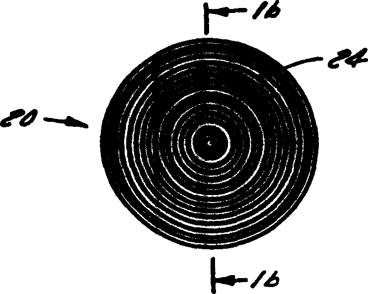
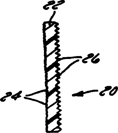
[0034] Based on the above-listed patents and pending applications assigned to the assignee of the present inventor, the assignee has developed a number of methods for optically or mechanically creating microetched surface structures randomly within a substrate and microstructure, and produce a light output with smooth consistent and continuous intensity. These microstructures can also be used to control the direction of light output from the light source so that the output light forms a desired distribution pattern or envelope. Published patents consist in the use of various means to form these surface structures in photoresist materials and to replicate these structures on sub-stencils. Using these sub-stencils it is also possible to replicate microstructures on sheets, which may be sandwiched, or another sheet applied to the object, in order to provide uniform, shaped and directional light . The pending application discloses other developed techniques to form these microst...


PUM


Abstract

A monolithic element (20) having a substrate (22) and at least one macroscopically optically characteristic entity (24) within a first portion of the optical element, a plurality of surface macrostructures (26) being integrated within the portion of the optical element . The macrostructure is designed to allow light to pass through the optical element uniformly, so that the smoothly changing discontinuous light emitted by the optical element has a predetermined pattern. Therefore, the light emitted by the optical basis can be changed according to the macroscopic properties of the optical element and the uniform properties of the macroscopic structure.

Description

technical field [0001] The present invention relates to the field of optics in general and, more particularly, to various optical elements employing whole surface diffusers as part of the optical element. Background technique [0002] Various types of optical components are used in large numbers for current and new applications. These optical elements are placed in a beam or path of light to alter the characteristics of the light passing through the optical element. These optical elements can be common simple cylindrical lenses, the beam entering the lens remains unaffected in its width, but the beam is broadened by the shape of the cylindrical mirror in the direction perpendicular to its width. An example of another optical element is a transparent medium with a flat surface on one side and a concave or convex surface on the other side to change the characteristics of the light passing through the lens. Such lenses are commonly used in spectacle glasses, magnifier glasses...

Claims


Application Information

Patent Timeline
Patent Type & Authority Patents(China)
IPC IPC(8): G02B3/08F21S8/10F21V8/00G02B3/00G02B3/06G02B5/02G02B5/04G02B5/18G02B5/30
CPCF21S43/237F21S43/239F21S43/245F21S43/249G02B5/021G02B5/0221G02B5/0268G02B5/0278G02B6/0038Y10S385/901G02B3/08
Inventor 里克·L·谢杰弗里·A·莱恩加金德拉·D·萨文特托马兹·P·杨森
Owner LUMINIT
Why Eureka
Try Eureka