
A manufacturing method and manufacturing equipment for a sealing ring fracture

A technology for manufacturing equipment and sealing rings, which is applied in the direction of manufacturing tools, metal processing equipment, feeding devices, etc., and can solve the problems of small diameter of sealing rings, large crack gaps, poor sealing performance, etc.

Active Publication Date: 2017-10-31
GUANGZHOU QUANDE MACHINERY TECH CO LTD
View PDF15 Cites 0 Cited by
  • Summary
  • Abstract
  • Description
  • Claims
  • Application Information

AI Technical Summary

Problems solved by technology

At present, the broken seam is formed on the sealing ring, and the gap of the broken seam is large. When the broken seam is formed, the diameter of the sealing ring will become smaller and cannot be used normally. Even if it can be used, the gap of the broken seam is large, so the sealing performance is poor. , In addition, the existing fracture accuracy is low, such as the phenomenon that the position of the fracture occurs, and the axis of the fracture and the sealing ring has an included angle

Method used


Image

  • A manufacturing method and manufacturing equipment for a sealing ring fracture
  • A manufacturing method and manufacturing equipment for a sealing ring fracture
  • A manufacturing method and manufacturing equipment for a sealing ring fracture

Examples


Embodiment Construction

[0026] The present invention will be further described in detail below in conjunction with the accompanying drawings and specific embodiments.

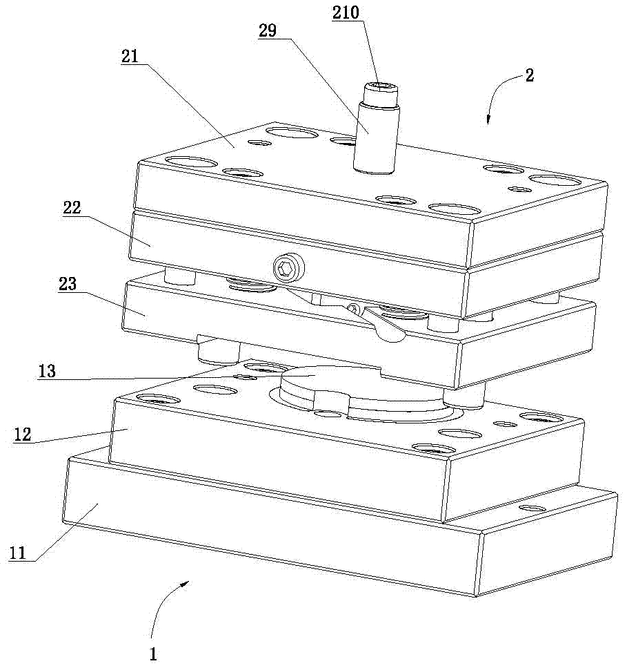
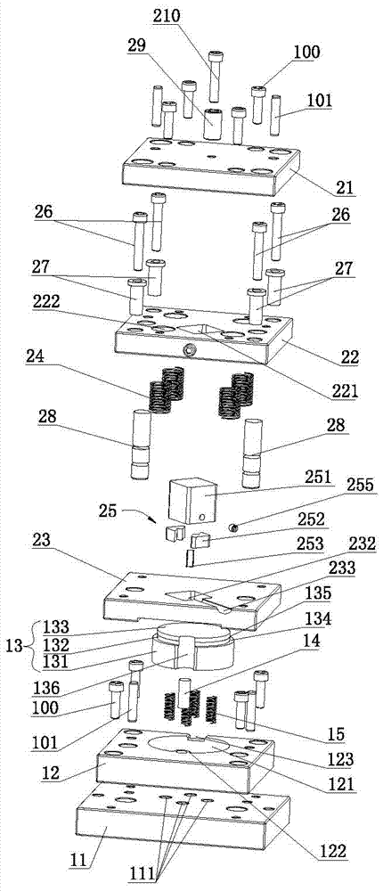
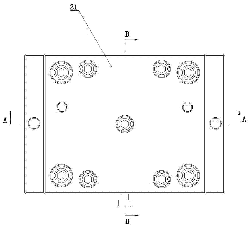
[0027] Such as Figure 1 to Figure 5 As shown, the manufacturing equipment for sealing ring fractures includes presses and molding dies.

[0028] Such as Figure 1 to Figure 5 As shown, the molding die includes a lower die 1 and an upper die 2 .

[0029] Such as figure 1 and Figure 5 As shown, the lower mold 1 includes a lower mold seat 11 , a lower mold positioning seat 12 , a positioning seat 13 , a bolt 100 and a positioning pin 101 .

[0030] The lower mold positioning seat 12 is fixed on the lower mold base 11 by bolts 100, and a positioning pin 101 passes through between the lower mold base 11 and the lower mold positioning base 12 to play a positioning role, ensuring that the lower mold fixing base 12 and the lower mold base Positioning accuracy between 11. Positioning holes 111 are provided on the lower mold base 11 . ...


PUM

PropertyMeasurementUnit
thicknessaaaaaaaaaa

Abstract

The invention discloses a manufacturing method and equipment for breaking joints of a sealing ring. The manufacturing equipment comprises a forming die, wherein the forming die comprises a lower die and an upper die; the lower die comprises a lower die seat, a lower die locating seat and a locating seat, the locating seat comprises a connecting portion, a limiting portion and a locating portion which are sequentially connected upwards, the connecting portion, the limiting portion and the locating portion gradually decrease in cross section, and a first elastic member is arranged between the bottom of the connecting portion and the lower die seat. The upper die comprises an upper die seat, an upper die fixing plate, a prepressing plate, a second elastic member and a cutting knife assembly; the cutting knife assembly is fixedly arranged on the upper die fixing plate and corresponds to the position of a yielding gap, the lower end of the cutting knife assembly is provided with a knife edge, and the thickness of the knife edge is 0.1-0.2mm; an accommodating groove which is in positional correspondence to the locating seat is formed in the bottom of the prepressing plate, and the accommodating groove is 0.2-0.5mm higher than the sealing ring. According to the manufacturing method, the forming die is used for forming the breaking joints. According to the method and the equipment, the breaking joints with small clearance and high accuracy can be formed on the sealing ring.

Description

technical field [0001] The invention relates to a manufacturing device and a manufacturing method for sealing ring fractures. Background technique [0002] The choice of sealing ring material is of great significance to its sealing performance and service life. The performance of the material directly affects the performance of the sealing ring. Sealing rings generally need to have the following properties. [0003] (1) High elasticity and resilience. [0004] (2) It has appropriate mechanical strength, including expansion strength, elongation and tear strength, etc. [0005] (3) The performance is stable, not easy to swell in the medium, and the heat shrinkage effect is small. [0006] (4) Easy to process and shape, and can maintain precise dimensions. [0007] (5) Do not corrode the contact surface, do not pollute the medium, etc. [0008] Sealing rings generally include O-rings, U-rings, V-rings, rectangular sealing rings, and Y-rings. [0009] For some rectangular...

Claims


Application Information

Patent Timeline
Patent Type & Authority Patents(China)
IPC IPC(8): B21D28/06B21D43/00
CPCB21D28/06B21D43/003
Inventor 陈永光
Owner GUANGZHOU QUANDE MACHINERY TECH CO LTD
Learn More