
Pipe machining equipment

A technology for processing equipment and pipes, which is applied in the field of pipe processing equipment, can solve problems such as easy generation of burrs and unsatisfactory cutting effect of steel pipes, and achieve the effects of reducing labor intensity, ideal cutting effect, and saving time

Inactive Publication Date: 2016-03-23
TIANJIN HUAYOU PETRO CHEM ENG CO LTD
View PDF7 Cites 7 Cited by
  • Summary
  • Abstract
  • Description
  • Claims
  • Application Information

AI Technical Summary

Problems solved by technology

[0003] In view of this, the present invention aims to propose a pipe processing equipment to solve the problems in the prior art, such as the unsatisfactory incision effect of the steel pipe, the easy generation of burrs and the realization of the quantifiable length of steel pipe cutting.

Method used


Image

  • Pipe machining equipment
  • Pipe machining equipment
  • Pipe machining equipment

Examples


Embodiment Construction

[0025] It should be noted that, in the case of no conflict, the embodiments of the present invention and the features in the embodiments can be combined with each other.

[0026] In describing the present invention, it should be understood that the terms "center", "longitudinal", "transverse", "upper", "lower", "front", "rear", "left", "right", " The orientations or positional relationships indicated by "vertical", "horizontal", "top", "bottom", "inner" and "outer" are based on the orientations or positional relationships shown in the drawings, and are only for the convenience of describing the present invention and Simplified descriptions, rather than indicating or implying that the device or element referred to must have a particular orientation, be constructed and operate in a particular orientation, and thus should not be construed as limiting the invention. In addition, the terms "first", "second", etc. are used for descriptive purposes only, and should not be understood ...


PUM

PropertyMeasurementUnit
Center line angleaaaaaaaaaa

Abstract

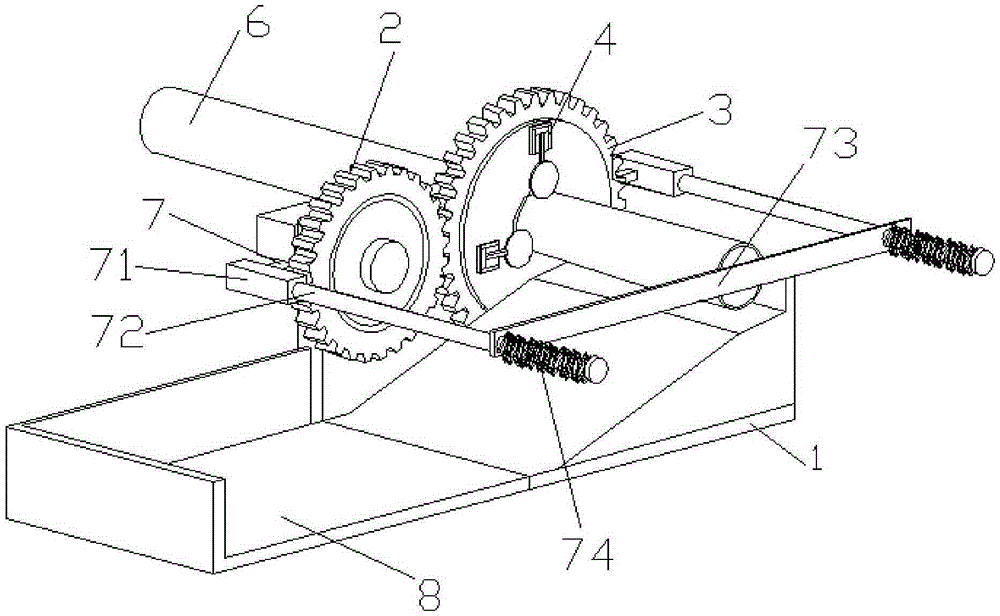
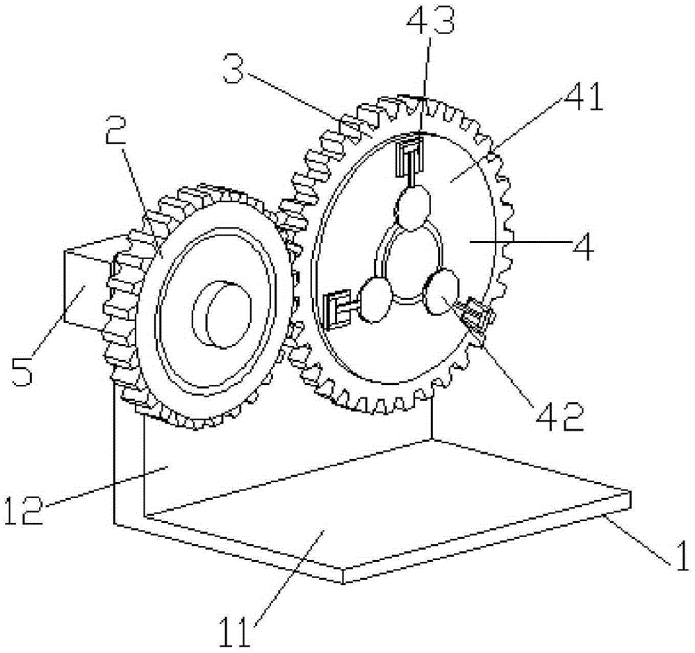
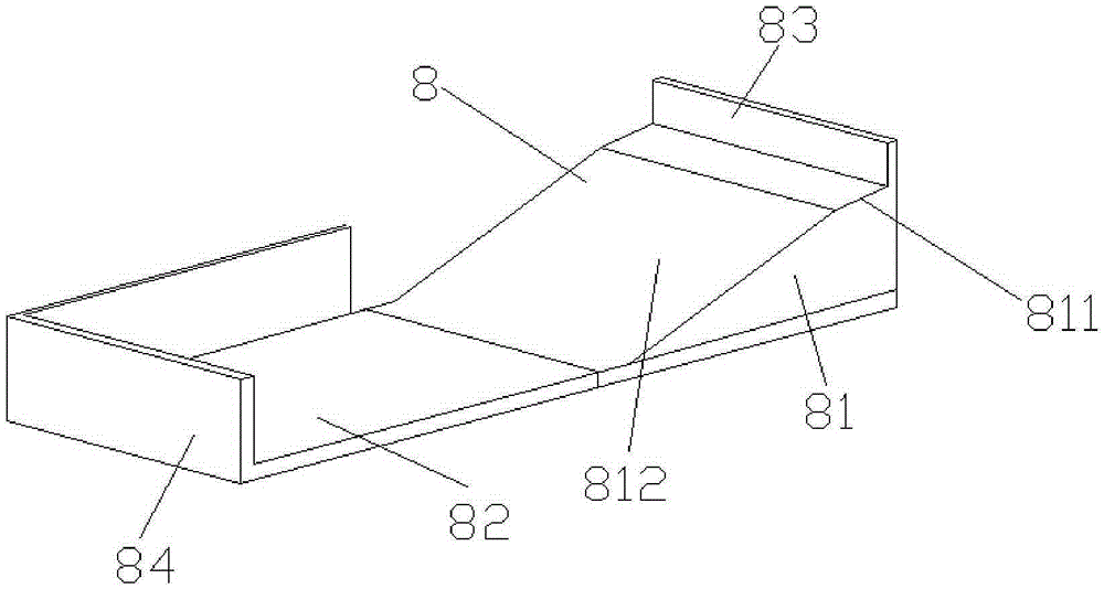
The invention provides pipe machining equipment. The pipe machining equipment comprises a fixing seat, a small gear, a big gear, a cutting assembly, a motor, measuring components and a collecting table, wherein the fixing seat comprises a baseplate and a side plate which are perpendicular to each other; the small gear is connected with one end of the side plate; the big gear is connected with the other end of the side plate; the cutting assembly is fixedly connected onto the gear in a parallel manner, coaxially arranged with the big gear, and comprises a plurality of cutters; the cutters are uniformly distributed on the outer circumference of a to-be-machined steel pipe, and in contact with the to-be-machined steel pipe; the measuring components are respectively arranged on two sides of the to-be-machined steel pipe; the collecting table is arranged below the to-be-machined steel pipe. The pipe machining equipment has the benefits that through arrangement of the cutters, the steel pipe cutting efficiency can be further improved when the uniform cutting force is guaranteed, so as to save time, improve the production efficiency, and achieve a more ideal cutting effect.

Description

technical field [0001] The invention belongs to the technical field of mechanical equipment, and in particular relates to a pipe material processing equipment. Background technique [0002] Currently. There is a great demand for steel pipes in the mechanical field, and steel pipes are used in many aspects of all walks of life, which is inseparable from cutting steel pipes into the sizes we need. In the prior art, for cutting steel pipes, grinding wheel cutting, cutting saws and the like are mainly used. During the cutting process of the steel pipe, due to the different cutting forces received by different parts of the steel pipe, for thin-walled steel pipes or steel pipes with small diameters, it is easy to deform or even produce burrs, which requires subsequent processing and wastes time; secondly, when cutting, Steel pipes often need to be cut into specific lengths. In the prior art, this purpose can only be achieved by manual measurement and marking. Not only is the acc...

Claims


Application Information

Patent Timeline
IPC IPC(8): B23D21/04B23D33/12B23D33/00
CPCB23D21/04B23D33/00B23D33/12
Inventor 薛晋澎
Owner TIANJIN HUAYOU PETRO CHEM ENG CO LTD
Learn More