Novel logistics unloading device

A technology of unloading device and logistics, applied in the directions of transportation and packaging, loading/unloading, etc., can solve the problems of endangering personal safety, affecting the safety of goods, prone to accidents, etc., and achieving the effect of ensuring personal safety and safe unloading

Inactive Publication Date: 2016-03-23
CHENGDU JIAMEIJIA SCI & TECH
View PDF5 Cites 2 Cited by
  • Summary
  • Abstract
  • Description
  • Claims
  • Application Information

AI Technical Summary

Problems solved by technology

[0002] With the development of the economy and the development of logistics transportation, the total amount of logistics transportation is also increasing. In the process of logistics transportation, when the logistics vehicle transports the goods to the destination, it is necessary to transfer the goods loaded on the logistics vehicle from the logistics vehicle For loading and unloading, at present, the unloading method is usually carried out manually, that is, the personnel standing on the logistics vehicle completely rely on manpower to transfer the goods on the vehicle to the personnel standing on the ground. This unloading method not only The efficiency is very low, and it is labor intensive, which greatly increases the labor intensity of the unloading personnel, and in the case of heavy cargo, direct handling and delivery are prone to accidents (especially when the unloading personnel are extremely fatigued after long-term work) , thus seriously endangering personal safety, but also greatly affecting the safety of goods

Method used


Image

  • Novel logistics unloading device

Examples


Embodiment Construction

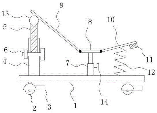
[0013] like figure 1 As shown, a new type of logistics unloading device includes a base plate 1 and a wheel 2 located at the bottom of the base plate 1, a wheel brake 3 is also provided at the wheel 2, and a casing 4 extending vertically is provided at the left end of the base plate 1 , there are many pairs of through holes (not shown in the figure) evenly distributed from top to bottom on the left and right sides of the sleeve 4, the first strut 5 is also embedded in the sleeve 4, and when the sleeve 4 When positioning bolts 6 are installed in one of the pair of through holes, the bottom end of the first pole 5 is against the positioning bolts 6;

[0014] On the bottom plate 1 on the right side of the casing 4, a second support rod 7 is vertically arranged, and a buffer plate 8 is also arranged on the second support rod 7. The unloading device also includes a first slide plate 9 and a second slide plate 10, wherein the right end of the first slide plate 9 is hinged with the ...


PUM


Abstract

The invention relates to a novel logistics unloading device. The novel logistics unloading device comprises a bottom plate and wheels. A sleeve is disposed at the left end of the bottom plate; multiple pairs of through holes are uniformly formed in the left side and the right side of the sleeve from top to bottom; a first fulcrum bar is embedded into the sleeve; a second fulcrum bar is vertically disposed on the bottom plate located on the right side of the sleeve; a buffer plate is further disposed on the second fulcrum bar. The unloading device further comprises a first sliding plate and a second sliding plate. The right end of the first sliding plate is hinged to the left end of the buffer plate; the left end of the first sliding plate makes contact with and abuts against the top end of the first fulcrum bar; the left end of the second sliding plate is hinged to the right end of the buffer plate; a rubber cushion block is further disposed at the right end of the bottom of the second sliding plate; a buffer spring is further connected between the bottom of the second sliding plate and the top of the bottom plate. By means of the structure, the novel logistics unloading device can conveniently, rapidly and safely unload goods, so that goods safety and personal safety of unloading staff are greatly guaranteed.

Description

technical field [0001] The invention relates to a novel logistics unloading device. Background technique [0002] With the development of the economy and the development of logistics transportation, the total amount of logistics transportation is also increasing. In the process of logistics transportation, when the logistics vehicle transports the goods to the destination, it is necessary to transfer the goods loaded on the logistics vehicle from the logistics vehicle For loading and unloading, at present, the unloading method is usually carried out manually, that is, the personnel standing on the logistics vehicle completely rely on manpower to transfer the goods on the vehicle to the personnel standing on the ground. This unloading method not only The efficiency is very low, and it is labor intensive, which greatly increases the labor intensity of the unloading personnel, and in the case of heavy cargo, accidents are prone to occur in direct transfer (especially when the u...

Claims


Application Information

Patent Timeline
IPC IPC(8): B65G67/24
CPCB65G67/24
Inventor 梁枫
Owner CHENGDU JIAMEIJIA SCI & TECH
Why Eureka
Try Eureka