
A hook capable of automatic hooking and unhooking

A hook and automatic technology, applied in the field of automatic hooking and decoupling hooks, hooks, can solve the problems of low work efficiency, hidden dangers, injury to staff, etc., and achieve convenient operation, collision prevention, strong automatic Effect

Active Publication Date: 2017-06-06
HENAN SINOKO CRANES
View PDF5 Cites 0 Cited by
  • Summary
  • Abstract
  • Description
  • Claims
  • Application Information

AI Technical Summary

Problems solved by technology

[0002] Hook is an important accessory in hoisting machinery. Hooks are usually used together with hoisting equipment such as cranes and cranes. They are often used in major ports, docks, and loading and unloading service companies for loading and unloading of goods; when lifting heavy objects, the hoisting The operation of hooking and unhooking the lifting object is all done manually, which requires the operator to stand in the working area to complete it. For the staff standing in the working area, there are potential safety hazards. Once the lifting object breaks down during the lifting process Swinging, it is easy to touch the staff, thereby injuring the staff; in addition, the manual operation of the unhook operation of the hook is relatively low in work efficiency, and it is difficult to unhook the large lifting object

Method used


Image

  • A hook capable of automatic hooking and unhooking
  • A hook capable of automatic hooking and unhooking
  • A hook capable of automatic hooking and unhooking

Examples


Embodiment 1

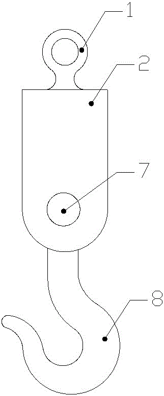
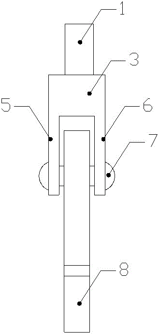
[0025] Such as Figure 1-6 As shown, a hook capable of automatic hooking and unhooking, it includes a suspension ring 1, the lower end of the suspension ring 1 is provided with a fixed plate 2, the fixed plate 2 is composed of a horizontal plate 3, a vertical plate 4, a side plate A5 and the side plate B6; the middle part of the side plate A5 and the side plate B6 passes through a hinge shaft 7, and the hinge shaft 7 is connected with a hook 8, and one side of the upper end of the hook 8 is opened. There is a hole A9, a cross bar A10 is arranged in the hole A9, a threaded hole 11 is arranged on the lower side of the hole A9, a threaded column 12 is arranged in the threaded hole 11, and the right end of the threaded column 12 is arranged There is a permanent magnet 13; a hole B14 is provided at the position opposite to the hole A9 on the vertical plate 4, and a cross bar B15 is arranged in the described hole B14, and a spring 16 is connected on the described cross bar B15. The...

Embodiment 2

[0028] Such as Figure 1-6 As shown, a hook capable of automatic hooking and unhooking, it includes a suspension ring 1, the lower end of the suspension ring 1 is provided with a fixed plate 2, the fixed plate 2 is composed of a horizontal plate 3, a vertical plate 4, a side plate A5 and the side plate B6; the middle part of the side plate A5 and the side plate B6 passes through a hinge shaft 7, and the hinge shaft 7 is connected with a hook 8, and one side of the upper end of the hook 8 is opened. There is a hole A9, a cross bar A10 is arranged in the hole A9, a threaded hole 11 is arranged on the lower side of the hole A9, a threaded column 12 is arranged in the threaded hole 11, and the right end of the threaded column 12 is arranged There is a permanent magnet 13; a hole B14 is provided at the position opposite to the hole A9 on the vertical plate 4, and a cross bar B15 is arranged in the described hole B14, and a spring 16 is connected on the described cross bar B15. The...


PUM


Abstract

The invention relates to a lifting hook capable of achieving automatic engagement and disengagement. The lifting hook comprises a lifting ring, and a fixing plate is arranged at the lower end of the lifting ring and composed of a transverse plate, a vertical plate, a side plate A and a side plate B. A hinged shaft penetrates the middle of the side plate A and the middle of the side plate B, and the hinged shaft is connected with a lifting hook body. A hole A is formed in one side of the upper end of the lifting hook body, a transverse rod A is arranged in the hole A, and a threaded hole is formed under the hole A. A threaded stud is arranged in the threaded hole. A permanent magnet is arranged at the right end of the threaded stud. A hole B is formed in the position, corresponding to the hole A, of the vertical plate. A transverse rod B is arranged in the hole B and connected with a spring, and the other end of the spring is connected with the transverse rod A. Corresponding to the permanent magnet, a hole C is arranged under the hole B. An electromagnet is arranged in the hole C, and the wire-winding end of the electromagnet protrudes out of the hole C. The lifting hook capable of achieving automatic engagement and disengagement has the beneficial effects of high practicability, convenient operation and the high automatic property.

Description

technical field [0001] The invention relates to a suspension hook, which belongs to the field of hoisting machinery, in particular to a suspension hook capable of automatic hooking and unhooking. Background technique [0002] Hook is an important accessory in hoisting machinery. Hooks are usually used together with hoisting equipment such as cranes and cranes. They are often used in major ports, docks, and loading and unloading service companies for loading and unloading of goods; when lifting heavy objects, the hoisting The operation of hooking and unhooking the lifting object is all done manually, which requires the operator to stand in the working area to complete it. For the staff standing in the working area, there are potential safety hazards. Once the lifting object breaks down during the lifting process Swinging, it is easy to touch the staff, thereby injuring the staff; in addition, the manual operation of the unhook operation of the hook has relatively low work eff...

Claims


Application Information

Patent Timeline
Patent Type & Authority Patents(China)
IPC IPC(8): B66C1/36B66C13/06
CPCB66C1/36B66C13/063
Inventor 崔丽单丙放胡哲涛刘继伟
Owner HENAN SINOKO CRANES
Learn More