Novel pipeline-type automatic dehydrater for oil tank

A pipeline type, dehydrator technology, applied in the field of dehydrators, can solve the problems of large maintenance and inaccurate monitoring, and achieve the effect of accurate and effective dehydration

Active Publication Date: 2016-03-23
GUANGZHOU DAY WO AUTOMATION IND
View PDF6 Cites 6 Cited by
  • Summary
  • Abstract
  • Description
  • Claims
  • Application Information

AI Technical Summary

Problems solved by technology

[0004] The purpose of the present invention is to solve the above-mentioned technical problems of inaccurate monitoring and large a

Method used


Image

  • Novel pipeline-type automatic dehydrater for oil tank
  • Novel pipeline-type automatic dehydrater for oil tank
  • Novel pipeline-type automatic dehydrater for oil tank

Examples


Embodiment 1

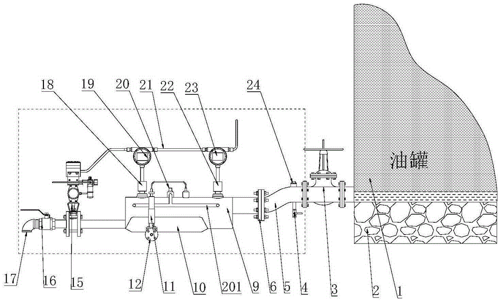
[0036] Such as figure 1 As shown, the novel pipeline type oil tank automatic dehydrator of the present invention includes a dehydration pipeline 9, a first sensor 22 arranged on the dehydration pipeline 9, a second sensor 18, and a first sensor connected to the first sensor 22. The controller 23, the second controller 19 connected to the second sensor 18, and the dehydration valve 15 for controlling the switch of the dehydration pipeline 9, the first sensor 22 and the second sensor 18 detect the oil and water passing through the dehydration pipeline 9 Proportion. The first controller 23 and the second controller 19 jointly control the opening and closing of the dehydration valve 15 according to the monitoring data fed back by the first sensor 22 and the second sensor 18 respectively.

[0037] Both ends of the dehydration pipeline 9 are respectively provided with a first mounting flange 6 and a second mounting flange, and one end of the first mounting flange 6 is connected to ...

Embodiment 2

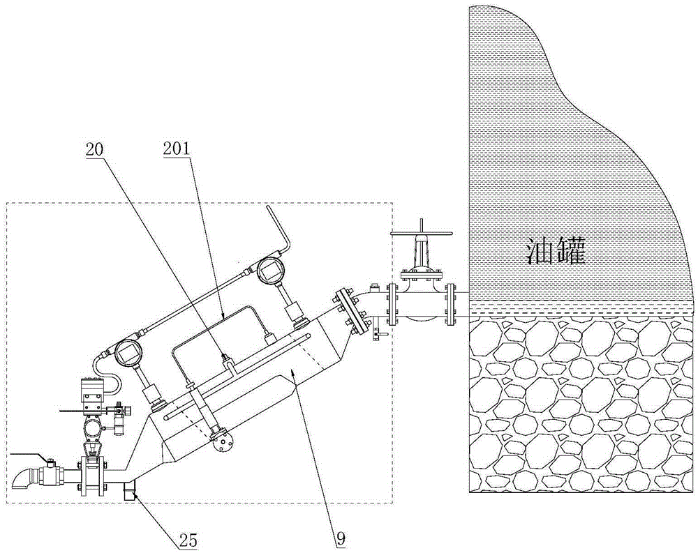
[0049] Such as figure 2 As shown, in this embodiment, except that the dehydration pipeline 9 is installed obliquely, other structures and working principles are the same as those in Embodiment 1. The dehydration pipeline 9 in this embodiment is installed obliquely, and the two ends of the dehydration pipeline 9 are respectively provided with eccentric big and small ends, and the eccentric big and small heads are integrally formed with the dehydration pipeline 9, and the small end of the eccentric big and small head is connected to the mounting flange connect. The first installation flange is connected with the oil tank 1 and is at a higher position, and the second installation flange is at a lower position for discharging water discharged through the dehydrator.

Embodiment 3

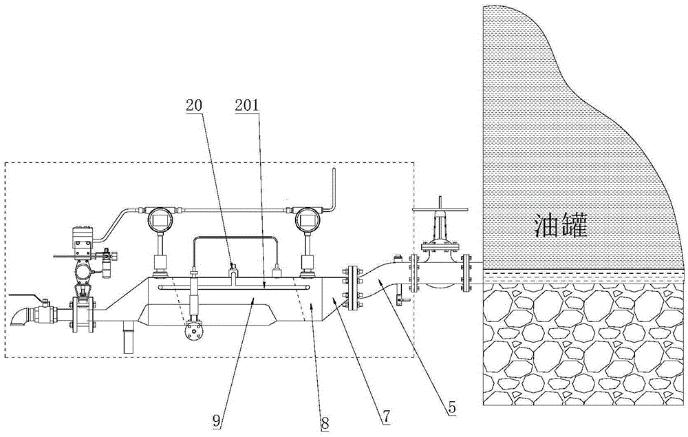
[0051] Such as image 3As shown, the new pipeline type oil tank automatic dehydrator described in this embodiment, except for the structure of the dehydration pipeline, other structures and working principles are the same as those in Embodiment 1, and the two ends of the dehydration pipeline 9 are respectively provided with first Eccentric small head 7, second eccentric small head 14, the dehydration pipeline 9 is horizontally arranged, one end of the small head of the first eccentric small head 7 is connected with the first mounting flange 6, the second eccentric small head 14 One end of the small head is connected with the second mounting flange.


PUM


Abstract

The invention discloses a novel pipeline-type automatic dehydrater for an oil tank. The novel pipeline-type automatic dehydrater comprises a dewatering pipeline, a first sensor arranged on the dewatering pipeline, a first controller and a dewatering valve, wherein the first controller is used for controlling opening or closing of the dewatering valve according to data detected by the first sensor; a first mounting part and a second mounting part are arranged at the two ends of the dewatering pipeline respectively; a cleaning pipeline is arranged in the dewatering pipeline; a cleaning pipeline inlet is formed in the dewatering pipeline; through the cleaning pipeline, a cleaning solution is introduced into the first sensor; the first mounting part is communicated with a water outlet of the oil tank; the second mounting part is not higher than the first mounting part. Through reasonable arrangement of the dewatering pipeline, impurities in the oil tank can flow out of the oil tank through the dewatering pipeline; the cleaning pipeline is arranged in the dewatering pipeline to realize cleaning of the sensor, so that the cleaning of the sensor is facilitated, and a problem that a dehydrater cannot work normally, which is caused by the fact that monitoring data is influenced due to pollution to the sensor is avoided.

Description

technical field [0001] The invention belongs to the technical field of dehydrators, and in particular relates to a novel pipeline type automatic dehydrator for oil tanks. Background technique [0002] Oil tank automatic dehydrator has been widely used in petrochemical storage tanks, replacing manual dehydration and providing great convenience for production. At present, most dehydrators are buffer tank structures. The water and oil at the bottom of the oil tank enter the buffer tank and settle to form an oil-water interface. The dehydration valve is controlled by detecting the height of the oil-water interface. However, during the dehydration process, impurities such as oil sludge and sand at the bottom of the oil tank will also enter the dehydrator and deposit at the bottom of the dehydrator, which requires regular cleaning and requires a lot of maintenance. When the oil-water density is not much different, the time to establish the oil-water interface is relatively long, ...

Claims


Application Information

Patent Timeline
IPC IPC(8): C10G33/08
CPCC10G33/08
Inventor 韩德福李鹏
Owner GUANGZHOU DAY WO AUTOMATION IND
Why Eureka
Try Eureka