Use method of bracket for projection equipment
A technology of projection equipment and support frame, applied in the field of cabinets or shelves, can solve the problems of inconvenient use, difficulty in adjusting the height of the support platform, etc.
- Summary
- Abstract
- Description
- Claims
- Application Information
AI Technical Summary
Problems solved by technology
Method used
Image

Examples
Embodiment 1
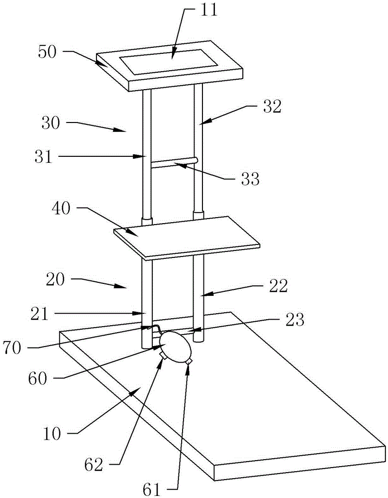
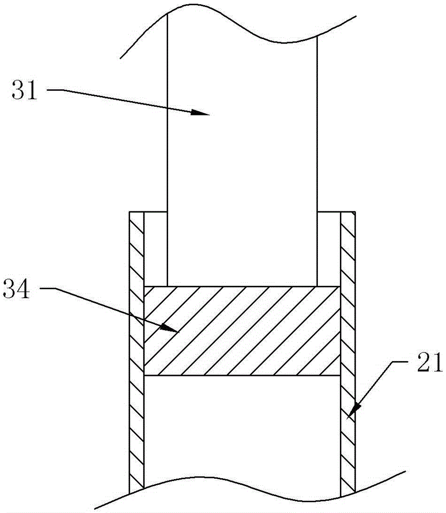
[0026] Embodiment 1 is basically as attached Figure 1-3 Shown: a method of using a bracket for projection equipment, the bracket includes a base 10, a first support frame 20, a second support frame 30, a first support platform 40 and a second support platform 50, and the first support frame 20 is installed on On the base 10, the first support frame 20 includes a communication pipe 23 and a first outer sleeve 21 and a second outer sleeve 22 arranged side by side, and the first outer sleeve 21 and the second outer sleeve 22 are connected by at least one communication pipe 23 , wherein a connecting pipe 23 is located at the bottom of the first outer sleeve 21 and the second outer sleeve 22; the first support platform 40 is installed between the first outer sleeve 21 and the second outer sleeve 22, and the second support platform 50 is installed at the second Between an inner sleeve 31 and the top of the second inner sleeve 32; the second support frame 30 includes a connecting pi...
Embodiment 2
[0034] Such as Figure 4As shown, the difference with Embodiment 1 is that: the base 10 is also provided with a sliding seat 70 and a seat 90 installed on the sliding seat 70, and the sliding seat 70 is horizontally slidably connected with the base 10; The spring 80 is connected on the sliding seat 70 . Seat 90 is connected by gas spring 80, then the height of seat 90 can be adjusted easily, thereby adapts to the use of people of different heights.
[0035] After step 2, the following steps are also included: the user adjusts the position of the sliding seat 70, and adjusts the height of the seat 90 through the gas spring 80, and then sits on the seat 90 to adjust the height of the projection device. The user can sit on the seat 90 to adjust the height of the projection device, and the sliding seat 70 is convenient for adjusting the position of the seat 90 to suit different users; at the same time, the user can also sit on the seat when performing a projection demonstration. ...
Embodiment 3
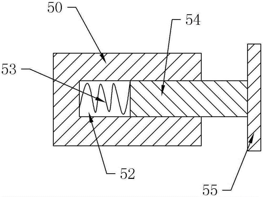
[0037] Such as Figure 5 As shown, the difference from Embodiment 2 is that: the second supporting platform 50 is provided with a positioning groove 51 for the projection device; the opposite side walls of the positioning groove 51 are provided with a positioning structure, and the positioning structure includes a sliding hole 52 , elastic piece 53, push rod 54 and collet 54, one end of push rod 54 is slidably connected in sliding hole 52 through elastic piece 53, and the other end is connected with collet 54, used elastic piece 53 is stage clip in the present embodiment.
[0038] Step 2 also includes the following steps: first push the ejector rod 54 to make the ejector rod 54 squeeze the compression spring, then put the projection device into the positioning groove 51, then release the ejector rod 54, the compression spring resets, and the clamp at one end of the ejector rod 54 The head 54 can hold the projection device in place. This can ensure the stability of the project...
PUM
 Abstract
Description
Claims
Application Information
 - R&D
- Intellectual Property
- Life Sciences
- Materials
- Tech Scout
- Unparalleled Data Quality
- Higher Quality Content
- 60% Fewer Hallucinations
Browse by: Latest US Patents, China's latest patents, Technical Efficacy Thesaurus, Application Domain, Technology Topic, Popular Technical Reports.
© 2025 PatSnap. All rights reserved.Legal|Privacy policy|Modern Slavery Act Transparency Statement|Sitemap|About US| Contact US: help@patsnap.com