
Tuning-fork type micro-electromechanical gyro sensitive structure with decoupling function

A technology of micro-electromechanical gyroscope and sensitive structure, which is applied in the direction of gyroscope/steering sensing equipment, gyroscope effect for speed measurement, measuring device, etc., which can solve the problems of output error, orthogonal coupling error, gyroscope performance impact, etc., and achieve reduction Effects of energy loss, coupling error suppression, and high sensitivity

Active Publication Date: 2016-03-23
BEIJING AUTOMATION CONTROL EQUIP INST
View PDF5 Cites 7 Cited by
  • Summary
  • Abstract
  • Description
  • Claims
  • Application Information

AI Technical Summary

Problems solved by technology

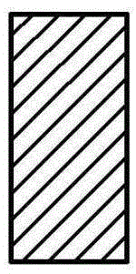
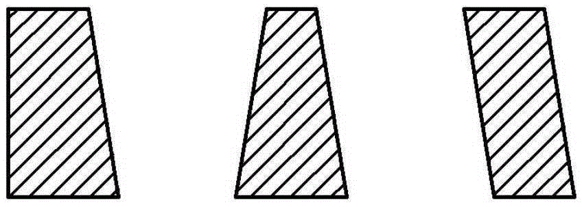
Ideally, the beam vibrates along its inertial axis, and the vibration direction is consistent with the driving or detection direction; in practice, due to machining errors, the actual cross-section of the beam deviates from the design value, as shown in Figure 2, its inertia The main axis is no longer coincident with the driving or detection direction, as shown in Figure 3, resulting in cross-coupling of driving and detection, resulting in output error, which is called quadrature coupling error, which has a great impact on the performance of the gyroscope

Method used


Image

  • Tuning-fork type micro-electromechanical gyro sensitive structure with decoupling function
  • Tuning-fork type micro-electromechanical gyro sensitive structure with decoupling function
  • Tuning-fork type micro-electromechanical gyro sensitive structure with decoupling function

Examples


Embodiment Construction

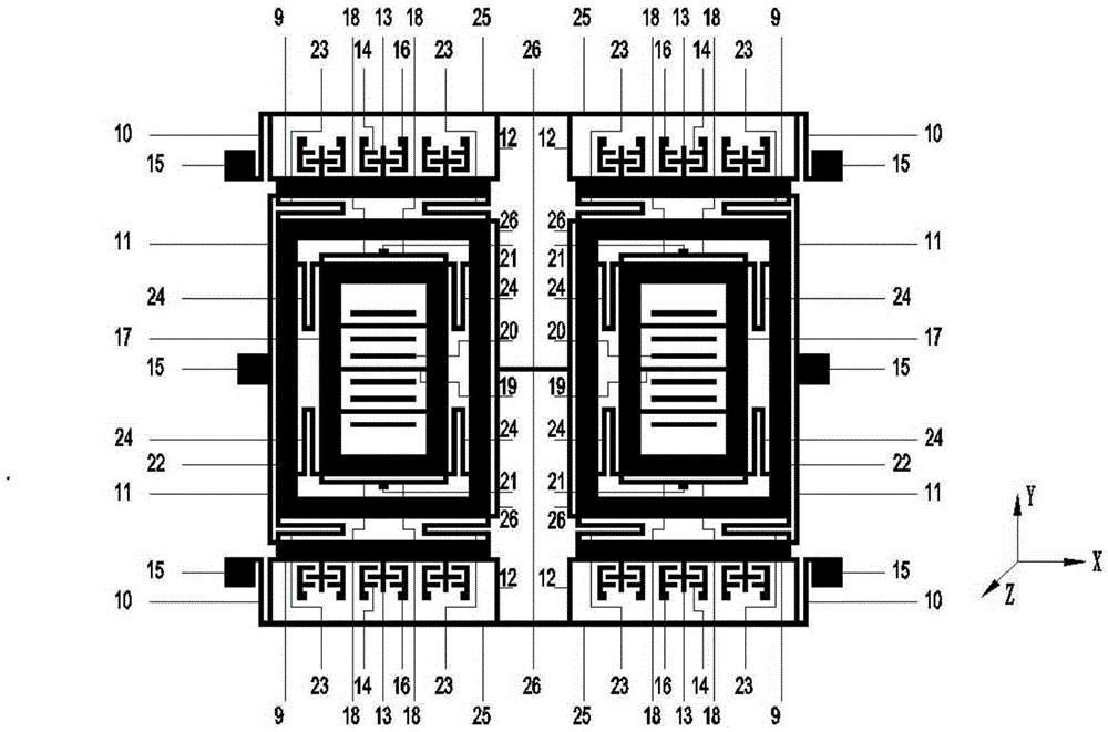
[0031] as attached Figure 4 As shown, a tuning-fork micro-electromechanical gyro sensitive structure with decoupling function is symmetrically distributed on the left and right sides. The entire sensitive structure includes a drive part, a detection part, a drive detection transfer part, a double-mass coupling part, and an orthogonal coupling error suppression part, etc.

[0032]The driving part is frame-shaped, and on the outermost side, it includes a driving mass 9, a U-shaped outer driving beam 10, a cantilever-shaped outer driving beam 11, a cantilever-shaped inner driving beam 12, driving moving comb teeth 13, driving fixed comb teeth 14, driving Anchor joint 15 and driving fixed comb teeth anchor joint 16 etc. Among them, the U-shaped outer driving beam 10, the cantilever-shaped outer driving beam 11, and the cantilever-shaped inner driving beam 12 are beams with degrees of freedom in the X direction, which can limit the movement of the driving part in the Y direction,...


PUM


Abstract

The invention belongs to a sensitive structure, and particularly relates to a tuning-fork type micro-electromechanical gyro sensitive structure with a decoupling function. The tuning-fork type micro-electromechanical gyro sensitive structure with the decoupling function is distributed in a left-right symmetric mode, and a left half body structure and a right half body structure are each composed of a driving frame, a driving detection switching frame and a detection frame, wherein the driving frame is arranged on the outermost side, the detection frame is arranged on the innermost side, the driving detection switching frame is arranged in the middle, and the left half body structure and the right half body structure are connected into a whole through the driving frames and the driving detection switching frames; each driving detection switching frame is provided with an orthogonal coupling error suppression structure. The tuning-fork type micro-electromechanical gyro sensitive structure with the decoupling function has the advantages that the symmetric type three-frame design is adopted, and the three frames are the driving frames, the driving detection switching frames and the detection frames; meanwhile, single-degree-of-freedom beams are adopted to connect all the frames, the degrees of freedom of motion of all the frames and mass blocks are limited, bidirectional decoupling between driving and detecting is achieved, and coupling errors can be suppressed to a large extent.

Description

technical field [0001] The invention belongs to a sensitive structure, in particular to a tuning fork micro-electromechanical gyro sensitive structure with a decoupling function. Background technique [0002] Gyroscope is an instrument used for angular movement of sensitive carrier relative to inertial space, and is the core device of inertial navigation and guidance system. [0003] MEMS gyro is a new type of inertial instrument manufactured based on microelectronics and micromechanical technology. It has the advantages of small volume, weight, power consumption, high integration, resistance to harsh environments, and low cost. [0004] The tuning-fork MEMS gyroscope based on the Gothic vibration principle is an important technical development direction of the MEMS gyroscope. Its structure is compact and the process is simple. It can be widely used in military fields such as precision-guided munitions and tactical missiles, as well as in the automotive industry and drilling...

Claims


Application Information

Patent Timeline
Patent Type & Authority Applications(China)
IPC IPC(8): G01C19/5747
CPCG01C19/5747
Inventor 郭中洋杨军刘飞盛洁窦茂莲胡兴雷崔健林梦娜刘凯
Owner BEIJING AUTOMATION CONTROL EQUIP INST
Learn More