
Push-pull photonic crystal zipper cavity optical accelerometer with electromagnetic feedback

A photonic crystal and accelerometer technology, used in the measurement of acceleration, velocity/acceleration/shock measurement, optics, etc., can solve the problems of difficult to achieve integrated monolithic integration, poor displacement control accuracy, and feedback hysteresis, etc. The effect of working bandwidth detection suppression, high reliability and small relative position error

Active Publication Date: 2022-07-15
ZHEJIANG UNIV
View PDF11 Cites 0 Cited by
  • Summary
  • Abstract
  • Description
  • Claims
  • Application Information

AI Technical Summary

Problems solved by technology

Electrostatic feedback utilizes the attractive or repulsive force between charges, and the stroke of the feedback is not large, which has the disadvantages of high driving voltage and small output force
Piezoelectric feedback is based on the piezoelectric effect of solid dielectrics, which will deform when voltage is applied. Although the drive response is fast and the displacement control accuracy is high, it is difficult to achieve integrated monolithic integration.
Thermal feedback uses the thermal expansion effect, but the displacement control accuracy is poor and the feedback has hysteresis

Method used


Image

  • Push-pull photonic crystal zipper cavity optical accelerometer with electromagnetic feedback
  • Push-pull photonic crystal zipper cavity optical accelerometer with electromagnetic feedback

Examples


Embodiment Construction

[0027] The present invention will be further described below with reference to the accompanying drawings and embodiments.

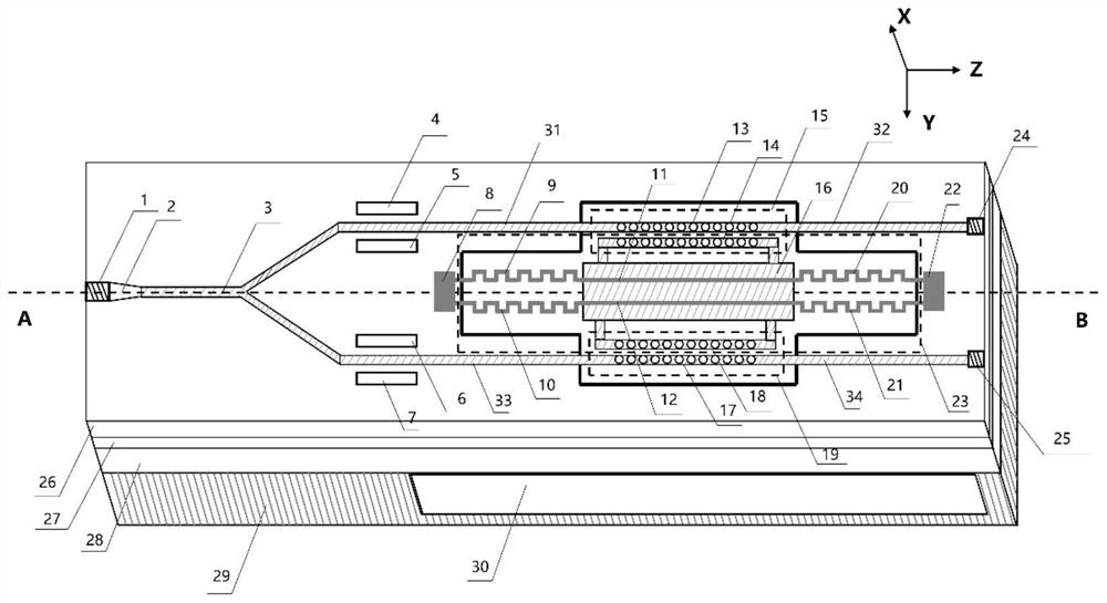
[0028] The Z axis of the optical accelerometer is the direction of its own central axis, the Y axis of the optical accelerometer is perpendicular to the Z axis, and the plane formed by the Y axis and the Z axis is parallel to the lithium niobate single crystal thin film layer 26 and the silicon dioxide buffer layer 27. At the interface, the X axis is perpendicular to the plane formed by the Y axis and the Z axis.

[0029] like figure 1 and figure 2 As shown, the optical accelerometer of the present invention is symmetrically arranged with respect to its central axis, including a narrow linewidth light source 1, a mode spot converter 2, a 1:2 Y-waveguide 3, a first upper electrode 4, a first lower electrode 5, The second upper electrode 6, the second lower electrode 7, the left driving electrode 8, the first photonic crystal upper nano-beam 13, the seco...


PUM


Abstract

The invention discloses a push-pull photonic crystal zipper cavity optical accelerometer with electromagnetic feedback. Light of a narrow linewidth light source is coupled through a spot size converter and enters a Y waveguide to realize light splitting, and light of a first branch end passes through a first input straight waveguide, a first upper nanometer micro beam and a first output straight waveguide and then is received by a first photoelectric detector. The light of the second branch end passes through a second input straight waveguide, a second lower nanometer micro beam and a second output straight waveguide and then is received by a second electric detector. The left driving electrode, the spring oscillator structure and the right driving electrode are respectively arranged between the first input straight waveguide and the second input straight waveguide, between the first upper nanometer micro-beam and the second lower nanometer micro-beam, and between the first output straight waveguide and the second output straight waveguide; the left driving electrode and the right driving electrode are electrically connected with the spring oscillator structure; and a permanent magnet is embedded in the ceramic base below the spring oscillator structure. According to the invention, high-resolution and large-bandwidth detection is realized, common-mode interference noise is suppressed, and the advantages of high integration level, large adjustable range and electromagnetic interference resistance are realized.

Description

technical field [0001] The invention belongs to an optical accelerometer in the technical field of integrated optics and inertial sensing, in particular to a push-pull photonic crystal zipper cavity monolithic integrated optical accelerometer with electromagnetic feedback. Background technique [0002] With the increasing maturity of microelectronic technology, integrated circuit technology and micro-processing technology, MOEMS accelerometer has many advantages such as strong anti-interference ability, suitable for strong electromagnetic interference and strong corruption environment, high sensitivity, small size and light weight. It is widely used in consumer electronics, agricultural automation, autonomous driving, medical equipment, aerospace, industrial robots and other fields. However, MOEMS accelerometers with technical solutions such as grating interference cavity type, F-P cavity type, Bragg grating type, and photonic crystal type cannot achieve both accuracy and ra...

Claims


Application Information

Patent Timeline
Patent Type & Authority Applications(China)
IPC IPC(8): G01P15/00G01D5/34G02B6/122G02B6/14G02B6/125
CPCG01P15/00G01D5/34G02B6/1225G02B6/14G02B6/125G02B2006/12152G02B2006/1204
Inventor 佘玄孙培基张奕群毕然陈侃舒晓武
Owner ZHEJIANG UNIV
Learn More