Restraining method for coupling error of micro silicon gyroscope with four mass blocks

A technology of silicon micromechanics and coupling error, which is applied in the design field of micro-inertial navigation system, can solve problems such as large coupling error output, large nonlinear error, and high difficulty, so as to suppress gyroscope coupling error, improve detection resolution, reduce Effect of measuring range

Active Publication Date: 2013-07-24
NAT UNIV OF DEFENSE TECH
View PDF2 Cites 1 Cited by
  • Summary
  • Abstract
  • Description
  • Claims
  • Application Information

AI Technical Summary

Problems solved by technology

The common problem now is that when the silicon micromachined gyro head and the supporting drive circuit work normally, there is only the component of the earth's rotation angular velocity under static conditions, so it can be approximately considered that the external angular velocity input is zero. However, through an oscilloscope or a spectrum analyzer It is clearly observed that the output signal of the sensitive end of the meter head - the Y-axis is very strong after the first demodulation, not zero and the amplitude is far greater than zero. At the same time, after the sensitive second demodulation, the zero deviation is very large
[0016] The above three methods have their own advantages and disadvantages. The first method tries to fundamentally eliminate the coupling error through manufacturing technology, but it is very difficult
In the second method, since the control method is not changed, the sensitive end of the silicon micromachined gyroscope still has a large mechanical coupling movement, which is far away from the linear range of detection and will introduce a large nonlinear error.
[0058] (5)C 0 ≠0 caused by signal suppression
However, the actual situation is that when the gyro is stationary, there is a large coupling error output, and the magnitude of the coupling error output is still quite large, and in some cases even the useful signal is completely submerged

Method used


Image

  • Restraining method for coupling error of micro silicon gyroscope with four mass blocks
  • Restraining method for coupling error of micro silicon gyroscope with four mass blocks
  • Restraining method for coupling error of micro silicon gyroscope with four mass blocks

Examples


Embodiment Construction

[0082] The present invention will be further described in detail below in conjunction with the accompanying drawings and specific embodiments.

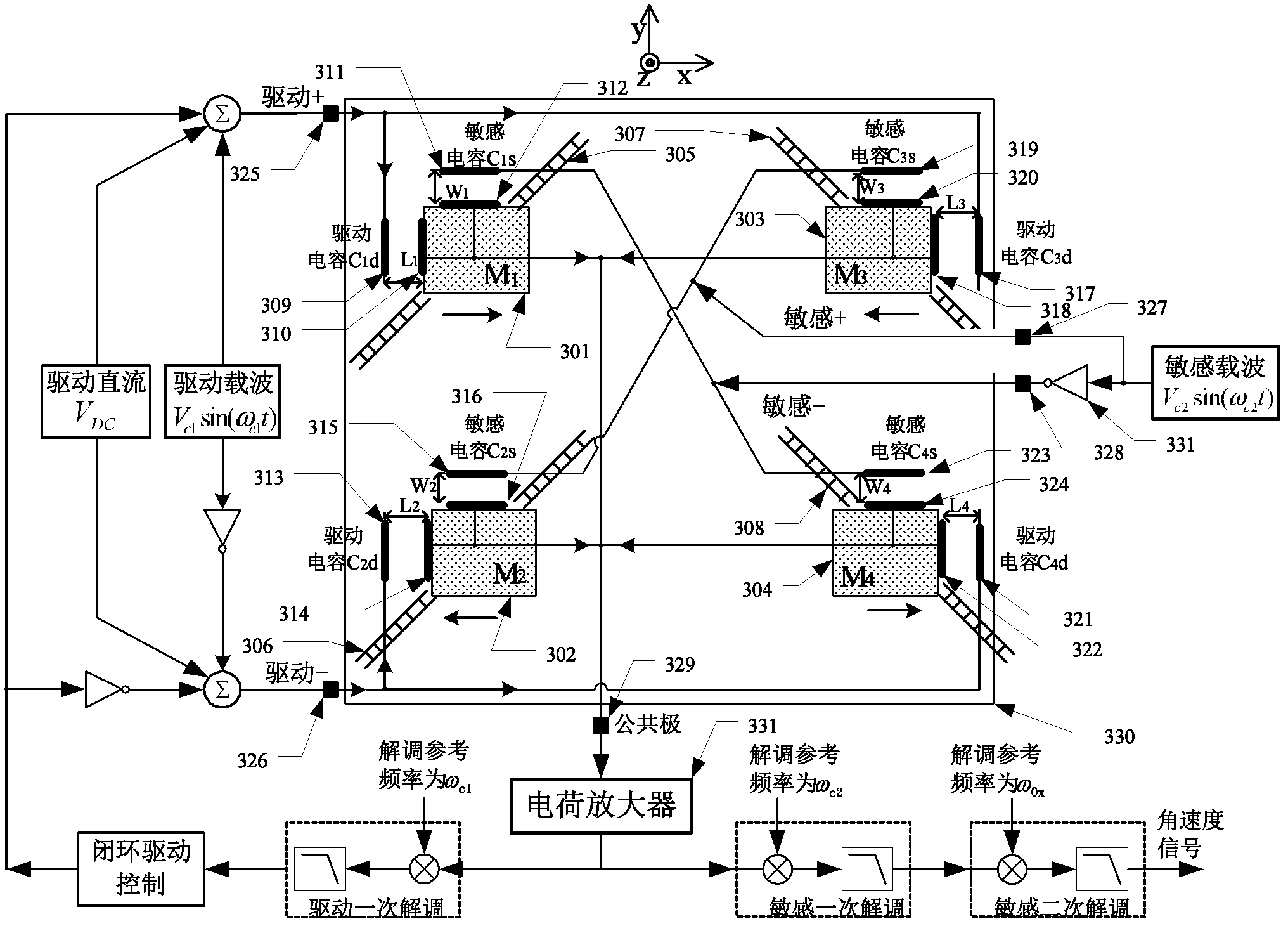
[0083] combine as Figure 5 Shown application example, the suppression method of four-mass silicon micromachined gyroscope coupling error of the present invention, its steps are:

[0084] 1. Divide the four mass blocks in the silicon micromachined gyro into two groups, and the silicon micromachined gyro head 528 is equivalent to a 7-terminal device: including drive 1+521, drive 1-522, drive 2+523, drive 2-524, sensitive +525, sensitive -526, public pole 527. Among them, drive 1+521 is connected to the original drive capacitor C 1d , drive 1-522 connected to the original drive capacitor C 2d . Drive 2+523 is connected to the original drive capacitor C 3d , drive 2-524 connected to the original drive capacitor C 4d . The connection relationship of the sensitive electrode remains unchanged, that is, the sensitive capacitance C 2s...


PUM


Abstract

The invention relates to a restraining method for a coupling error of a micro silicon gyroscope with four mass blocks, and the method comprises the following steps: (1) dividing the four mass blocks in the micro silicon gyroscope into two groups and taking following seven end components as gauge heads of the micro silicon gyroscope: a driver 1+, a driver 1-, a driver 2+, a driver 2-, a sensor +, a sensor - and a common pole; (2) arranging a master driving loop and a slave driving loop for independently controlling the two groups of mass blocks; and (3) pre-calibrating and presetting a drivingdirect current VDC2 value for the slave driving loop, thereby eliminating the coupling error of an output signal demodulated by the common pole, a high-pass filter 0 and the sensor -. The restrainingmethod for the coupling error of the micro silicon gyroscope with four mass blocks has the advantages that the principle is simple, the maneuverability is excellent, the restraining method can be easily popularized and applied, and the like.

Description

technical field [0001] The invention mainly relates to the design field of a micro-inertial navigation system, in particular to a coupling error suppression method applied to a four-mass silicon micro-mechanical gyroscope. Background technique [0002] Silicon micromechanical gyroscope is the core sensor of sensitive angular velocity in the micro inertial navigation system. It has the advantages of small size, light weight, low cost, and easy mass production. It has broad application prospects in military and civilian fields. [0003] The silicon micromachined gyroscope relies on the principle of vibration mechanics to detect the Coriolis acceleration to measure the rotational angular velocity. It belongs to the rate type gyroscope. Its basic principle is as follows: figure 1 Shown: [0004] figure 1 It is an uncoupled shared mass system, which includes an X-direction spring 101, a Y-direction spring 104, a mass 102, an X-direction damper 103, and a Y-direction damper 105,...

Claims


Application Information

Patent Timeline
Patent Type & Authority Patents(China)
IPC IPC(8): G01C19/5733
Inventor 罗兵胡小平江明明吴美平王旭王安成庹洲慧范永振刘伟吴学忠肖定邦陈志华
Owner NAT UNIV OF DEFENSE TECH
Why Eureka
Try Eureka