Tuning fork type micro-electro-mechanical gyroscope

A micro-electromechanical gyro and tuning fork type technology, applied in the field of inertial measurement, can solve the problems of difficult to improve gyro performance, low energy transfer efficiency, and inability to form resonance, etc., to suppress external common-mode interference, improve environmental adaptability, and reduce energy loss effect

Active Publication Date: 2016-11-23
BEIJING AUTOMATION CONTROL EQUIP INST
View PDF5 Cites 3 Cited by
  • Summary
  • Abstract
  • Description
  • Claims
  • Application Information

AI Technical Summary

Problems solved by technology

[0006] 1) It is difficult to completely decouple the driving and detection motion
Tuning-fork MEMS gyroscopes include two operating modes: driving and detection. Most of the existing tuning-fork MEMS gyroscopes can only realize the decoupling of a single direction of driving (or detection), and cannot effectively isolate the motion of driving / detection in two different directions. Introduce coupling error, gyro performance is difficult to improve
figure 1 To simplify the model of a typical single-direction decoupling sensitive structure, define the X direction as the driving direction, and the Y direction as the detection direction, then figure 1 (a) The model can only achieve decoupling of driving modes, figure 1 (b) The model can only achieve detection mode decoupling
figure 2 for figure 1 (a) A schematic diagram of a typical structure corresponding to the model. The main structure is a two-frame design, including the outer driving frame and the inner detection frame. The motion of the proof mass 4 and the driving mass 2 in the driving X direction cannot be effectively isolated
[0007] 2) The energy transfer efficiency between tuning fork masses is low
Most of the detection modes of the existing gyro-sensitive structure dual-mass blocks have not achieved coupling, which cannot effectively realize energy transfer and cannot suppress external common-mode interference
like image 3 A simplified model of a sensitive structure is shown. There is no energy transfer between the double masses and no resonance can be formed. Therefore, in its working mode, there will be phase difference, frequency difference, large energy loss and low sensitivity.

Method used


Image

  • Tuning fork type micro-electro-mechanical gyroscope
  • Tuning fork type micro-electro-mechanical gyroscope
  • Tuning fork type micro-electro-mechanical gyroscope

Examples


Embodiment Construction

[0021] A kind of dual decoupling, large capacitance tuning fork type MEMS gyro sensitive structure of the present invention is introduced below in conjunction with accompanying drawing and embodiment:

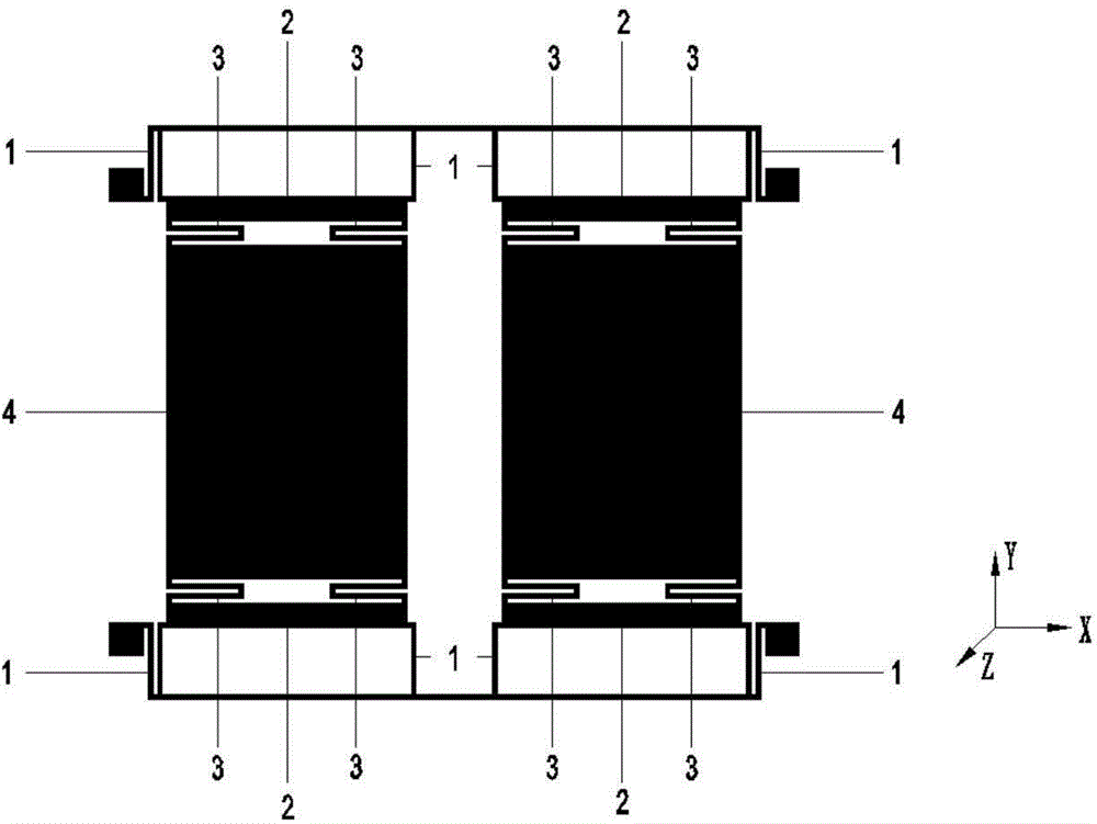
[0022] Such as Figure 4 As shown, the following coordinate system is established: the positive direction of the X-axis is to the right in the horizontal direction, the positive direction of the Y-axis is upward in the vertical direction, and the Z-axis is perpendicular to the plane formed by the X-axis and the Y-axis, and conforms to the right-hand rule.

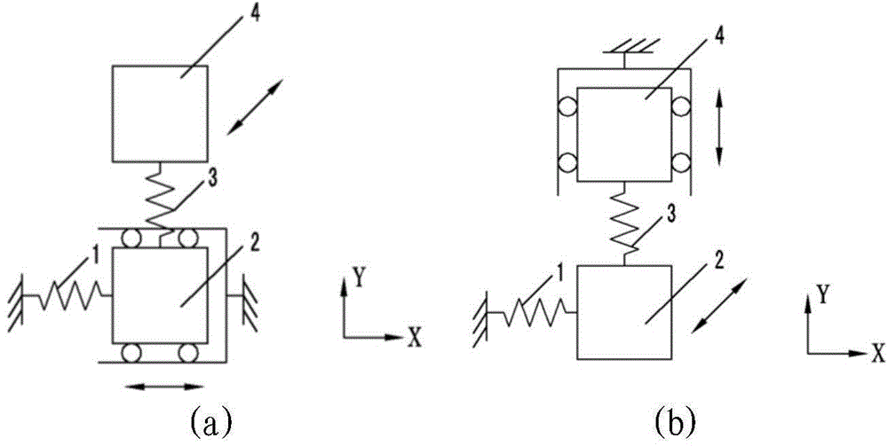
[0023] A double-decoupling, large-capacitance tuning-fork micro-electromechanical gyroscope is symmetrically distributed left, right, up and down, and the left and right halves of the main structure are composed of three frames: a drive frame, a drive detection transfer frame, and a detection frame. The entire sensitive structure includes a driving part, a detecting part, a driving-detecting transfer part and a double-mass c...


PUM


Abstract

The invention belongs to the technical field of inertial measurement and particularly relates to a micro-electro-mechanical gyroscope. The tuning fork type micro-electro-mechanical gyroscope comprises a driving portion, a detecting portion, a driving detection adapter portion and a double-mass-block coupling portion and is arranged in layout in a bilateral symmetry mode, the left portion or the right portion is arranged in a vertical symmetry mode, and the left portion or the right portion comprises a driving portion, a detecting portion, a driving detection adapter portion and a double-mass-block coupling portion. The tuning fork type micro-electro-mechanical gyroscope has the advantages that coupling errors can be inhibited, energy loss can be reduced, high sensitivity can be obtained, the phase difference and frequency difference problems caused by coupling absence and low coupling can be solved, and the adaptive capacity to environment of the gyroscope can be improved.

Description

technical field [0001] The invention belongs to the technical field of inertial measurement, and in particular relates to a micro-electromechanical gyroscope. Background technique [0002] Gyroscope is an instrument used for angular movement of sensitive carrier relative to inertial space, and is the core device of inertial navigation and guidance system. [0003] MEMS gyro is a new type of inertial instrument manufactured based on microelectronics and micromechanical technology. It has the advantages of small volume, weight, power consumption, high integration, resistance to harsh environments, and low cost. [0004] The tuning-fork MEMS gyroscope based on the Gothic vibration principle is an important technical development direction of the MEMS gyroscope. Its structure is compact and the process is simple. It can be widely used in military fields such as precision-guided munitions and tactical missiles, as well as in the automotive industry and drilling detection. civilia...

Claims


Application Information

Patent Timeline
Patent Type & Authority Applications(China)
IPC IPC(8): G01C19/5621
Inventor 郭中洋杨军刘飞盛洁崔健王登顺林梦娜
Owner BEIJING AUTOMATION CONTROL EQUIP INST
Why Eureka
Try Eureka