
Stator and rotor mounting machine applied to motor production and assembling

A chip loading machine, stator and rotor technology, applied in the manufacture of stator/rotor body, etc., can solve the problems of uneven assembly quality, high labor intensity, low labor efficiency, etc., and achieve reasonable installation layout, high degree of automation, and simple structure Effect

Active Publication Date: 2016-03-23
安徽创研新材料有限公司
View PDF9 Cites 0 Cited by
  • Summary
  • Abstract
  • Description
  • Claims
  • Application Information

AI Technical Summary

Problems solved by technology

In the prior art, the pressure of the stator and rotor is generally manually loaded, which has low labor efficiency, high labor intensity, long construction period, and uneven assembly quality, which cannot meet the requirements of modern production.

Method used


Image

  • Stator and rotor mounting machine applied to motor production and assembling
  • Stator and rotor mounting machine applied to motor production and assembling
  • Stator and rotor mounting machine applied to motor production and assembling

Examples


Embodiment Construction

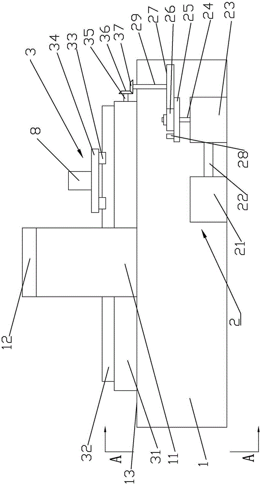
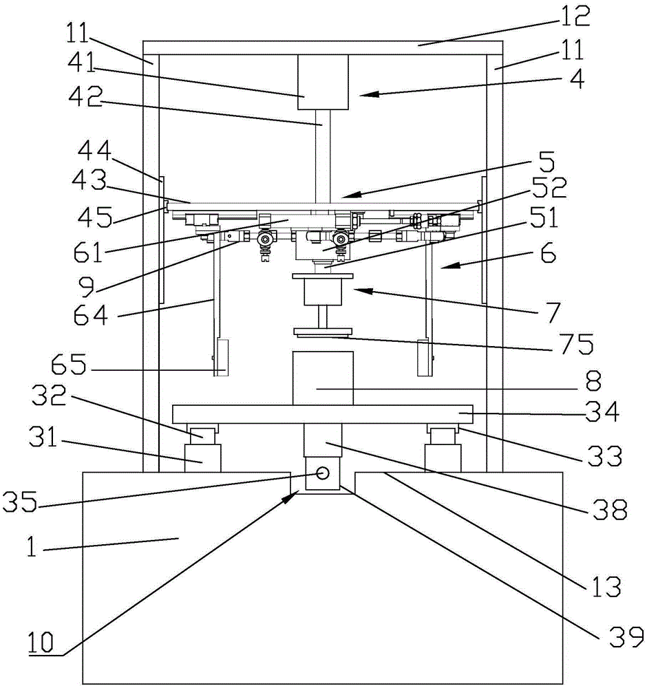
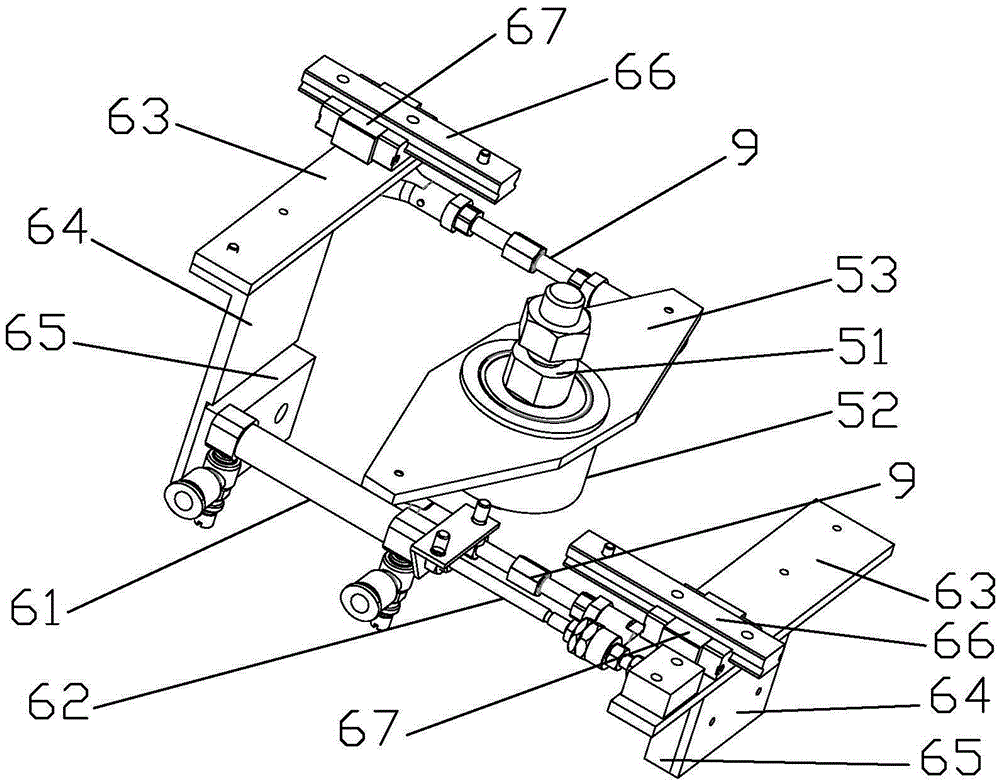
[0029] Such as Figure 1 to Figure 7 As shown, a stator and rotor chip loading machine applied to the production and assembly of electric motors includes a frame 1 and a frame platform 13. The frame platform 13 is located on the frame 1, and the frame platform 13 is provided with a conveying plate 34 and a loading plate. frame. A conveying carrier 8 is provided on the conveying plate 34. The conveying plate 34 is connected with an intermittent conveying device. The intermittent conveying device includes a conveying mechanism 3 and an intermittent transmission mechanism 2. The conveying mechanism 3 is connected to the intermittent transmission mechanism 2. The transmission mechanism 2 is located in the frame 1. The loading frame includes two loading vertical frames 11 and a horizontal loading frame 12. The loading vertical frame 11 is installed and fixed on the rack platform 13, and the loading vertical frame 11 is located on both sides of the conveying plate 34. The two loadin...


PUM


Abstract

The invention discloses a stator and rotor mounting machine applied to motor production and assembling. The stator and rotor mounting machine comprises a rack and a rack platform; the rack platform is positioned on the rack; the rack platform is provided with a material conveying flat plate and a mounting frame; the material conveying flat plate is connected with an interval material conveying apparatus; the interval material conveying apparatus comprises a material conveying mechanism and an interval transmission mechanism; the material conveying mechanism is connected with the interval transmission mechanism; the mounting frame comprises two mounting vertical frames and a mounting transverse frame; the mounting transverse frame is provided with a lifting mounting apparatus; the lifting mounting apparatus is connected with a centering apparatus; the centering apparatus comprises a centering rotating shaft, a centering disk and a centering rotating table; the centering rotating shaft is mounted below the lifting mounting apparatus; the centering disk and the centering rotating table are mounted on the centering rotating shaft; and a mounting assembly is mounted under the centering rotating table. The stator and rotor mounting machine is simple in structure, scientific and convenient, highly targeted, high in automation degree, and capable of realizing assembly line assembling of the motor stators and rotors and well solving the problem existing in the assembling of the motor stators and rotors.

Description

Technical field [0001] The invention relates to a stator and rotor chip loading machine applied to the production and assembly of motors. Background technique [0002] The stator and rotor of the motor are the key components of the motor. The quality of the stator and rotor manufacturing directly affects the quality and life of the motor manufacturing. The stator and rotor are generally stamped and assembled after molding. In the prior art, the stator and rotor are generally manually loaded, which has low labor efficiency, high labor intensity, long construction period, and uneven assembly quality, which cannot meet modern production requirements. In order to solve the above problems, a device for assembling the stator and rotor is needed to complete the assembly line of the stator and rotor. Summary of the invention [0003] The purpose of the present invention is to provide a stator and rotor chip loading machine applied to motor production and assembly. The machine has simple ...

Claims


Application Information

Patent Timeline
Patent Type & Authority Applications(China)
IPC IPC(8): H02K15/02
CPCH02K15/02
Inventor 过兆达
Owner 安徽创研新材料有限公司
Learn More