Stamping equipment applied to motor stator and rotor sheet production

A technology of stamping equipment, stator and rotor, applied in the field of stamping equipment, can solve the problems of low production efficiency, poor product quality, high labor intensity, etc., and achieve the effects of good stamping effect, simple structure and reduced labor intensity.

Active Publication Date: 2016-03-23
南通捷越机电有限公司
View PDF8 Cites 4 Cited by
  • Summary
  • Abstract
  • Description
  • Claims
  • Application Information

AI Technical Summary

Problems solved by technology

[0003] When the existing stator and rotor punching process is performed, the rotor shaft hole, each rotor slot, and each stator slot are stamped slot by slot. The stamping die can only punch one slot hole for each stamping, and the steps of stamping slot holes are the same as those of the rotor.

Method used


Image

  • Stamping equipment applied to motor stator and rotor sheet production
  • Stamping equipment applied to motor stator and rotor sheet production
  • Stamping equipment applied to motor stator and rotor sheet production

Examples


Embodiment Construction

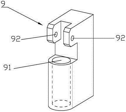
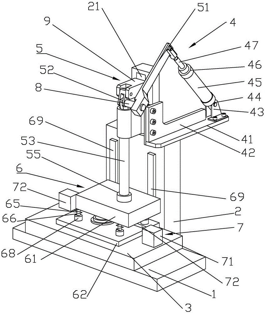
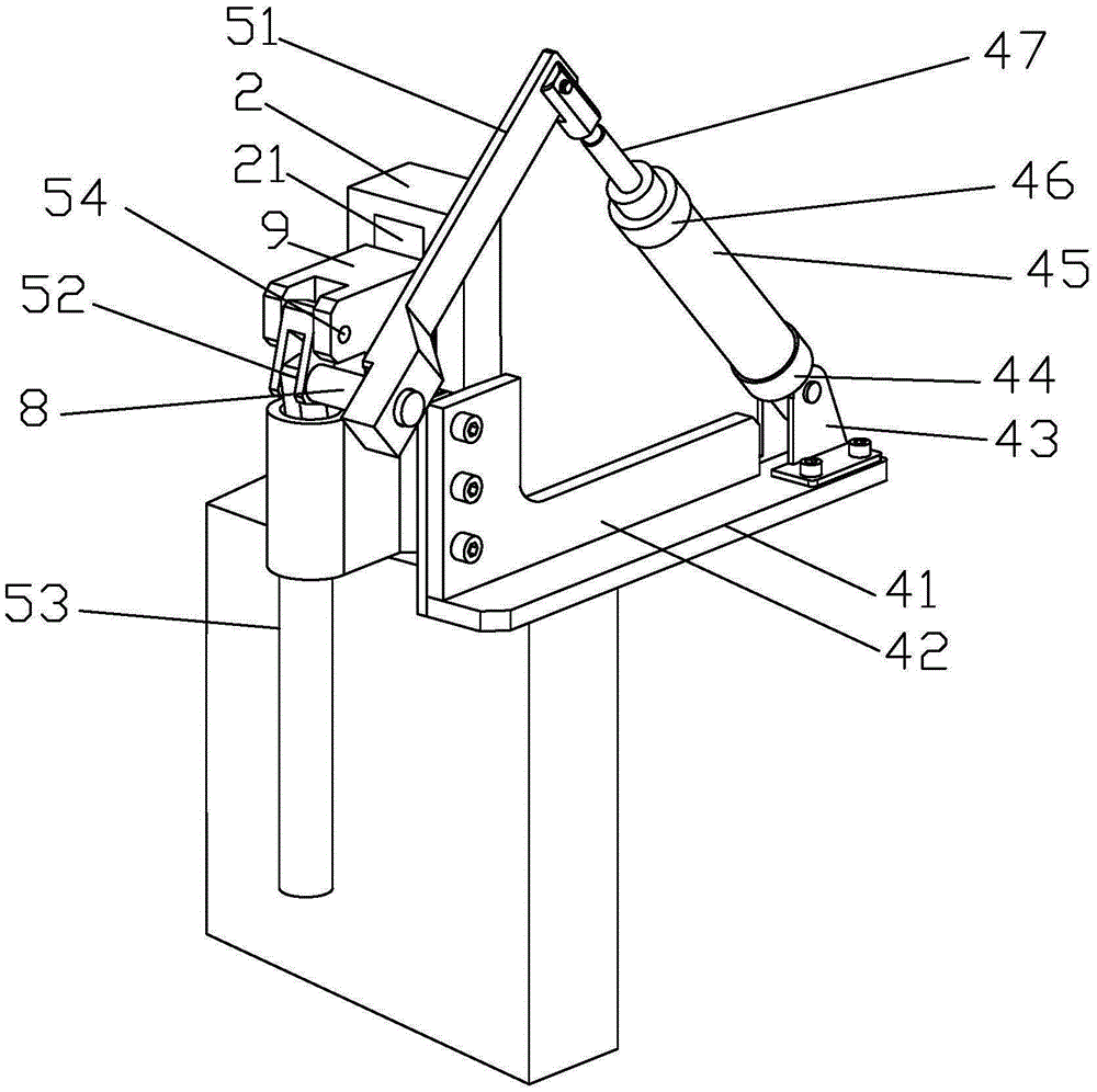
[0033] Such as Figure 1 to Figure 9 As shown, a stamping equipment applied to the production of motor stator and rotor pieces includes a stamping machine base 1 and a stamping machine body 2, the stamping machine body 2 is located on one side of the stamping machine base 1, and a stamping platform 3 is provided on the stamping machine base 1. The platform 3 is located in the middle of the punching machine base 1, the pressing device 7 is arranged on the punching platform 3, and the punching device is arranged on the punching machine body 2. The stamping device includes a stamping drive mechanism 4, a stamping transmission mechanism 5 and a stamping assembly 6. Both the stamping drive mechanism 4 and the stamping transmission mechanism 5 are installed on the stamping machine body 2. The stamping drive mechanism 4 is connected to the stamping transmission mechanism 5, and the stamping transmission mechanism 5 is connected to the stamping Component6. The stamping assembly 6 inc...


PUM


Abstract

The invention discloses stamping equipment applied to motor stator and rotor sheet production. The stamping equipment comprises a stamping engine base and a stamping engine body; a stamping apparatus comprises a stamping driving mechanism, a stamping transmission mechanism and a stamping assembly; the stamping driving mechanism is connected with the stamping transmission mechanism; the stamping transmission mechanism is connected with the stamping assembly; the stamping assembly comprises a stamping base, a stamping plate, a telescopic spring and a telescopic rod; the stamping base is glidingly mounted on the stamping engine body; the stamping plate is positioned below the stamping base; the stamping plate is mounted on a stamping platform; the telescopic rod is arranged between the stamping base and the stamping plate; and the telescopic spring is arranged on the telescopic rod. The stamping apparatus drives the whole equipment to move through the stamping driving mechanism; the stamping operation is performed by the stamping assembly under the drive of the stamping transmission mechanism; and the stamping equipment is simple in structure, good in stamping effect, safe, reliable and capable of improving the production efficiency of the stator and rotor sheet processing, lowering the labor intensity of workers and greatly improving the quality of products.

Description

technical field [0001] The invention relates to stamping equipment used in the production of motor stator and rotor slices. Background technique [0002] Motor stator and rotor punching sheets are usually laminated with 0.5mm thick silicon steel sheets, and then fixed on the stator and rotor brackets or shafts. Pole motors, synchronous asynchronous motors, etc. are widely used. For the finished motor, the punching sheet plays a more critical role in the motor accessories. In order to improve the overall performance of a motor, it is necessary to improve the punching performance of the punching sheet, and at the same time improve the production efficiency. [0003] When the existing stator and rotor punching process is performed, the rotor shaft hole, each rotor slot, and each stator slot are stamped slot by slot. The stamping die can only punch one slot hole for each stamping, and the steps of stamping slot holes are the same as those of the rotor. The steps of punching a...

Claims


Application Information

Patent Timeline
IPC IPC(8): H02K15/02B21D28/22B21D22/02
CPCB21D22/02B21D28/22H02K15/024
Inventor 过兆达
Owner 南通捷越机电有限公司
Why Eureka
Try Eureka