Quick-clamping jig for printed boards and method of use

A technology for clamping tooling and printed boards, which is applied in the manufacture of printed circuits, printed circuits, electrical components, etc. It can solve the problems that flying probes cannot be used for testing and cannot be clamped, and it is easy to move and carry, and the tooling is compact , flexible and convenient operation

Active Publication Date: 2018-03-16
TIANJIN 712 COMM & BROADCASTING CO LTD
View PDF6 Cites 0 Cited by
  • Summary
  • Abstract
  • Description
  • Claims
  • Application Information

AI Technical Summary

Problems solved by technology

[0004] In the past, in the flying probe test of printed boards with components, if there are components within 5mm from the clamped edge of the printed board, this printed board cannot be clamped, so the flying probe cannot be used to test this equipment.

Method used


Image

  • Quick-clamping jig for printed boards and method of use
  • Quick-clamping jig for printed boards and method of use
  • Quick-clamping jig for printed boards and method of use

Examples


Embodiment Construction

[0021] Such as Figures 1 to 7 As shown, a printed board fast clamping fixture includes a base 1 , a jacket 2 , a guide rod 3 , a spring 4 , a magnet 5 , and an O-ring 6 .

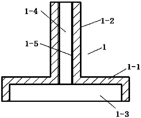
[0022] The base 1 is composed of an integral circular surface 1-1 and a circular tube 1-2, a circular groove 1-3 is provided on the circular surface 1-1, and a circular tube 1 is arranged at the center of the circular groove 1-3 inner surface. -2 are communicated through holes 1-4, and threads 1-5 are provided on the inner wall of the through holes 1-4.

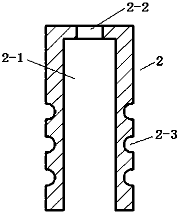
[0023] Overcoat 2 is cylindrical, is provided with circular groove 2-1 on one end face of overcoat 2, is provided with the hole 2-2 that communicates with circular groove 2-1 on the surface of overcoat 2 other end, on the surface of overcoat 2 Three semicircular grooves 2-3 are arranged at intervals on the outer wall.

[0024] Guide rod 3 is made of integral small circular surface 3-1 and cylinder 3-2, and one end of small cylinder 3-2 is provided with ...


PUM


Abstract

The invention relates to a printed-board rapid clamping tooling clamp and a usage method thereof. The clamp comprises a pedestal, an outer sleeve, a guide bar, a spring, a magnet and O-shaped rings. The tooling clamp is placed on an iron plate plane. A whole tooling clamp is firmly adsorbed on an iron plate. Portions of the three O-shaped rings on the outer sleeve are held and are pressed downwardly. The outer sleeve moves downwardly on a circular pipe of the pedestal. At this time, an upper end surface of the outer sleeve and a small round surface of the guide bar generate a segment of spacing gap. A printed board is put into the gap. The outer sleeve is not pressed by the hand right now. Through an effect of the spring, the outer sleeve moves upwardly on the circular pipe of the pedestal. The printed board is clamped in the gap between the upper end surface of the outer sleeve and the small round surface of the guide bar. By using the clamp and the method, an installation and clamping speed is fast; operation is flexible and convenient; the tooling is small, which is convenient for moving and carrying.

Description

technical field [0001] The present invention relates to a quick-clamping jig for printed boards and a method of use thereof, which are used in the clamping of printed boards when scraping solder paste on printed boards and the clamping of printed boards when dispensing glue in the process of BGA re-soldering , The clamping of the printed board during the flying probe test of the printed board. Background technique [0002] In the past BGA resoldering, when scraping the solder paste on the printed board, it is necessary to use some books of different thicknesses as pads and place them on the four corners of the printed board with components to ensure that the printed board is parallel to the workbench, but this It’s just a sense of parallelism, but it doesn’t actually guarantee that the printed board is truly parallel to the workbench, and the printed board will move back and forth, left and right in this way, which affects the quality of scraping solder paste. [0003] In t...

Claims


Application Information

Patent Timeline
Patent Type & Authority Patents(China)
IPC IPC(8): H05K3/00
CPCH05K3/00H05K2203/0165
Inventor 张庆宝
Owner TIANJIN 712 COMM & BROADCASTING CO LTD
Why Eureka
Try Eureka