Cabinet bearing mechanism used for communication cabinet

A technology of bearing mechanism and communication cabinet, applied in the direction of support structure installation, etc., can solve the problems of difficult processing, non-adjustable width, reduced versatility, etc., and achieve the effect of simple and convenient connection, high efficiency and firm connection

Inactive Publication Date: 2016-03-23
SUZHOU YUANSHUO PRECISION MOLD
View PDF3 Cites 3 Cited by
  • Summary
  • Abstract
  • Description
  • Claims
  • Application Information

AI Technical Summary

Problems solved by technology

[0005] 1. When it is necessary to make full use of the width space in the communication cabinet, part of the width space cannot be used because the width of the profiles used in the communication cabinet cannot be adjusted.
[0006] 2. The width of the installation strips in the existing communication cabinets cannot be adjusted, so it is necessary to design various installation strip structures to meet different width requirements, resulting in complex structure of the installation strips in the cabinet, difficult processing, and increased number of parts, making assembly difficult
[0007] 3. When it is necessary to make full use of the height space in the communication cabinet, because the height of the profile used in the communication cabinet cannot be replaced, part of the height space cannot be used directly; and after adding communication equipment, the original installation strip with weaker bearing capacity needs to be replaced. When using a larger installation strip, it cannot be quickly replaced and installed due to size adjustment restrictions, and even the entire communication cabinet needs to be reprocessed, which not only wastes resources, but also increases costs and reduces versatility

Method used


Image

  • Cabinet bearing mechanism used for communication cabinet
  • Cabinet bearing mechanism used for communication cabinet

Examples


Embodiment Construction

[0024] Below in conjunction with accompanying drawing of description, the present invention will be further described.

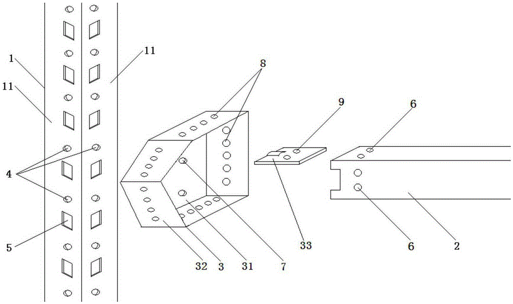
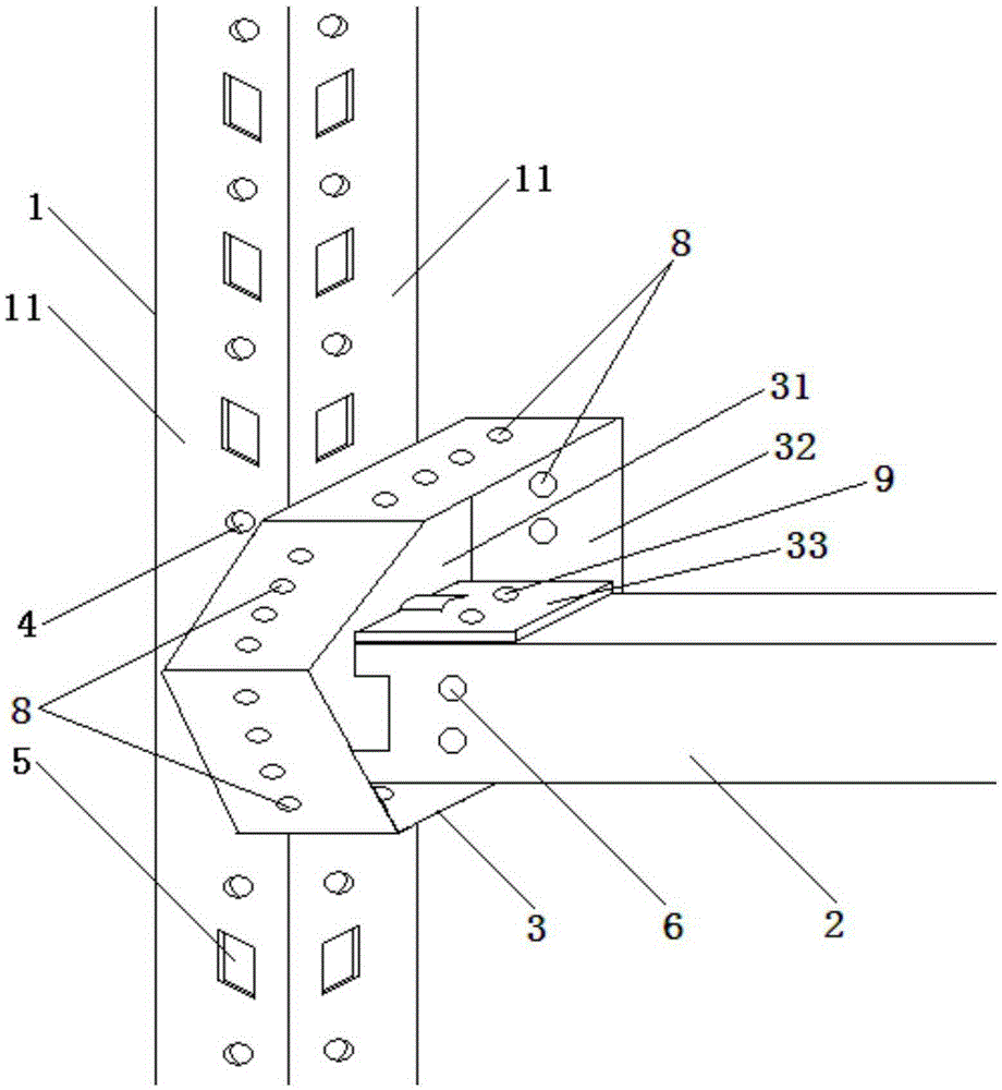
[0025] Such as figure 1 with figure 2 The shown load-carrying mechanism suitable for the communication cabinet includes a vertically distributed column 1 and a horizontally distributed installation bar 2, and the installation bar 2 is connected to the column 1 through an adapter plate 3; There is at least one row of equidistant through holes on the cylinder surface, the column 1 is a hollow square channel, and two rows of equally spaced circular bolt hole-shaped channels are opened on the column surface 11 along the axial length direction of the column 1. Hole 4, two rows of through holes 4 are respectively located on adjacent two cylindrical surfaces 11; the cylindrical surface 11 of the column 1 along the axial length direction is provided with square holes 5 that are coaxial and equidistantly distributed with the through holes 4, so that The square hol...


PUM


Abstract

The invention discloses a cabinet bearing mechanism used for a communication cabinet. The mechanism comprises a stand column and a mounting bar. The mounting bar is connected to the stand column through a changeover disc. The stand column is provided with a through hole. End portion of the mounting bar is provided with a fixing hole. The changeover disc comprises a supported circular plate which is vertically distributed and is connected to the stand column and a polygon ring which is vertically connected to the supported circular plate. A plate surface of the supported circular plate is provided with at least one installing hole matching with the through hole. An annular wall of each surface of the polygon ring is provided with row holes which are distributed at intervals and correspond to the fixing hole. The changeover disc is penetrated into the installing hole through a fastener, is locked with the through hole and then is fixed to the stand column. The mounting bar is penetrated into the fixing hole of a bottom surface of the mounting bar through a locking component, is vertically locked with the row holes of the annular wall of any surface, is penetrated into the row holes of the annular walls of the two adjacent surfaces in the polygon ring, is locked with the fixing holes of two side surfaces of the mounting bar along an inclination direction and then is fixed to the changeover disc. A width and a height of the mounting bar are flexible and adjustable and a space in the cabinet is fully used.

Description

technical field [0001] The invention relates to a bearing mechanism, in particular to an in-cabinet bearing mechanism suitable for a communication cabinet, and belongs to the technical field of communication equipment structures. Background technique [0002] Communication cabinets are required to be equipped with bearing parts because they are used to place various equipment as required. [0003] At present, the load-bearing parts used in the communication cabinets on the market are flat plates or installation strips erected between the vertical supports. root columns to form a rectangular support body. The amount of raw materials used for such bearing parts is high, and there is a defect of waste of raw materials. [0004] At the same time, there are the following shortcomings in the use of the installation strips used in the existing communication cabinets: [0005] 1. When it is necessary to make full use of the width space in the communication cabinet, part of the wi...

Claims


Application Information

Patent Timeline
Patent Type & Authority Applications(China)
IPC IPC(8): H05K7/14
Inventor 何婷朱磊
Owner SUZHOU YUANSHUO PRECISION MOLD
Why Eureka
Try Eureka